New Machine Build 8020 mill... long winded post, 56K killer. - Page 2


Page 2 of 3 FirstFirst 123 LastLast
Results 21 to 40 of 50

Thread: 8020 mill... long winded post, 56K killer.

  1. #21
    Registered
    Join Date
    Apr 2009
    Location
    USA
    Posts
    69
    Downloads
    0
    Uploads
    0

    Default

    Quote Originally Posted by thoug View Post
    Are you using the same patio door roller bearings for your gantry X and Y axis as you are for your cable tensioners?
    No, the patio door rollers are only for the cable tension set up. The X and Y rollers are detailed here:

    http://www.cnczone.com/forums/showpo...93&postcount=1

    Geeks did use the patio door rollers for his X and Y axis but reported that when he put the butcher boy bearings in, he was able to run faster speeds.

    Once I get my VNT-17 toy all set up in my BEW (car project), I'll get back on the CNC mill project... I'm going to see about making the gantry shorter, and will then start dialing in the bearings so that everything is squared up.


  2. #22
    Registered
    Join Date
    Apr 2009
    Location
    USA
    Posts
    69
    Downloads
    0
    Uploads
    0

    Default

    Finally something to update about. Been working on the mill on and off. Lots of lessons learned... like this whole "make it up as I go along" isn't the best way to do this because it kind of turns into "crap, didn't figure on this happening" very often. But I'm doing this for fun, and having to do all the problem solving so far has been a blast.

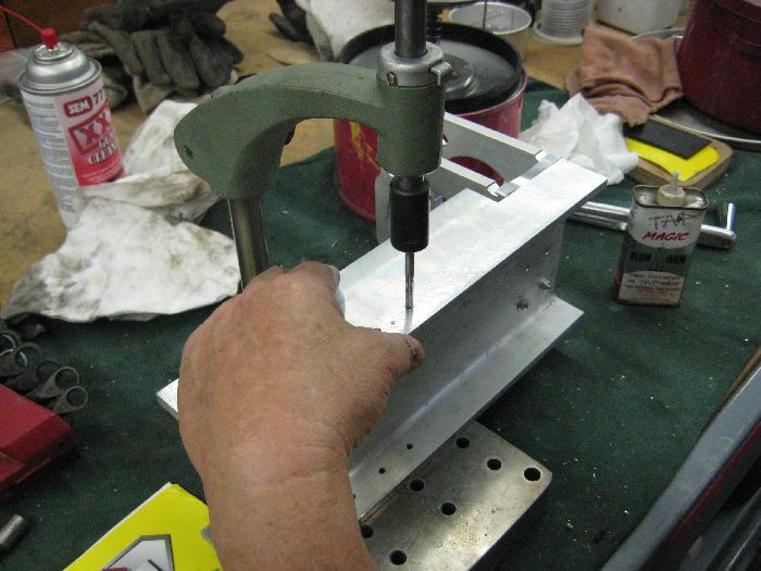
    So, I ended up taking apart the base to add hardware to it, I cut a bunch of the #3279 economy T nuts I had on hand into 2 pieces and put then though out the base so that I could secure #4302 90deg 2 hole joining plates, these will be to help secure a MDF platform to the base. Had to also take the gantry apart a little bit as well to add a few #3279 economy T nuts as well.

    From CNCRouterparts.com I ordered the following:

    1/2-10 ACME Nut, 5 Start - I picked up 3 of them
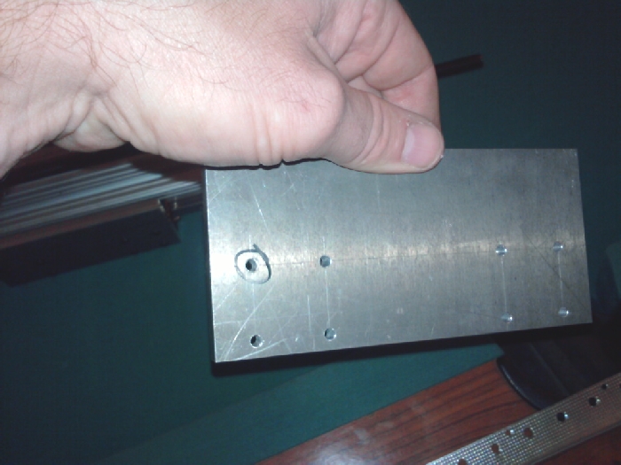
    Bearing Block and Cover - just 4 of them for now
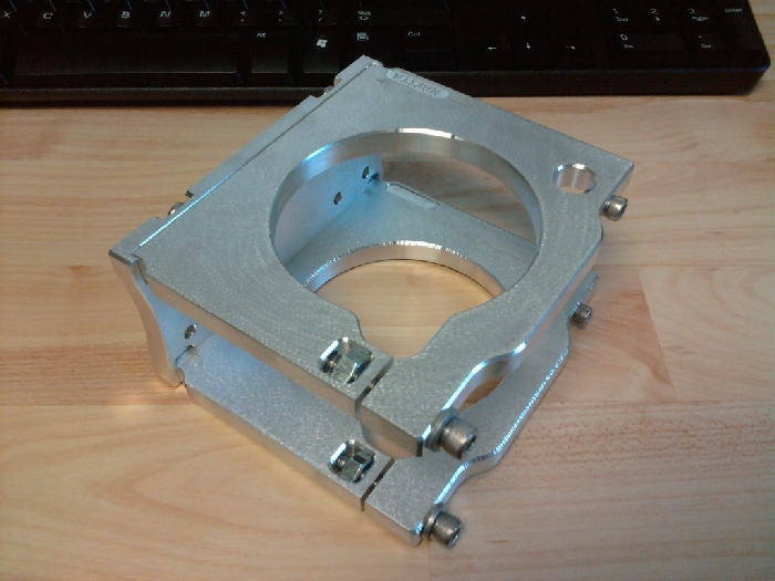
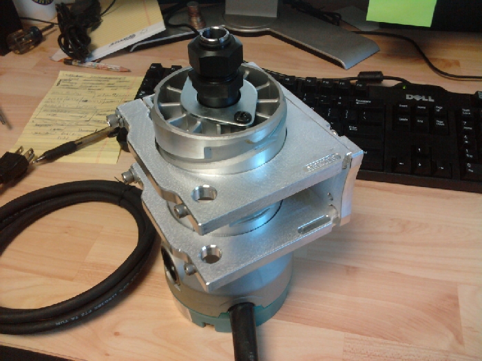
    NEMA 23 Motor Mount - 3 of them
    Zero Backlash Helical Shaft Coupler - 3 of them
    CNC Motor Cable - 3 of them

    From McMaster-Carr I purchased:

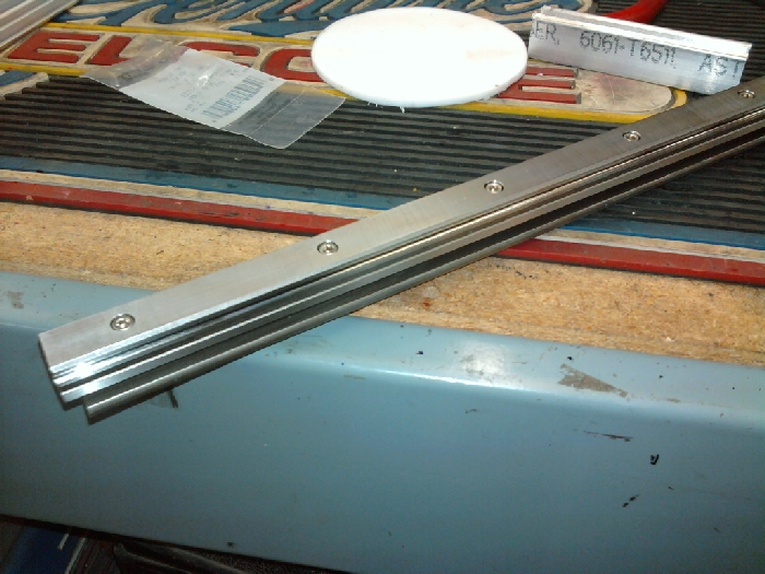
    Acme 1/2", 5 start rods, two 3 foot units and one 6 foot unit.
    1/2" sleeve clamps, 4 units
    1/2" thrust washers and needle bearings - 4 complete sets

    So, lets get some stepper motors finally bolted onto this puppy.

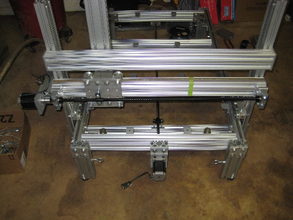
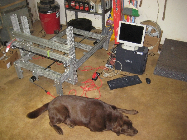
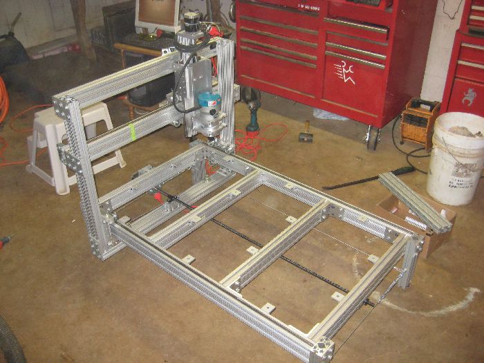
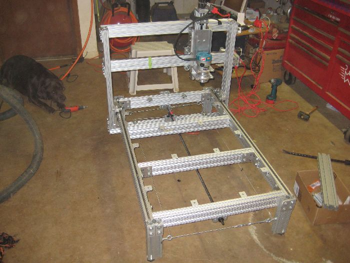
    An overall shot of where I stand:


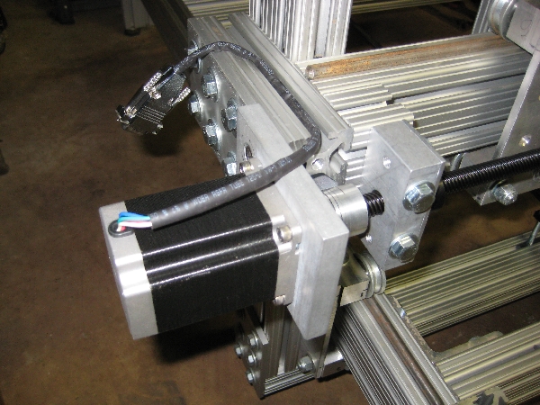
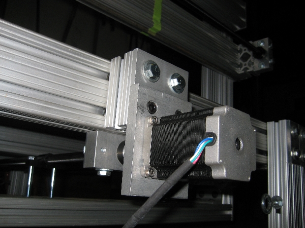
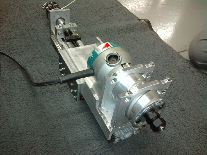
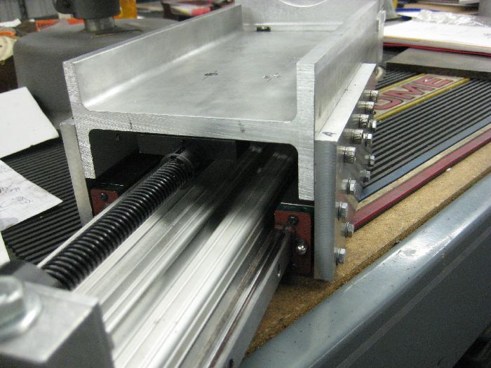
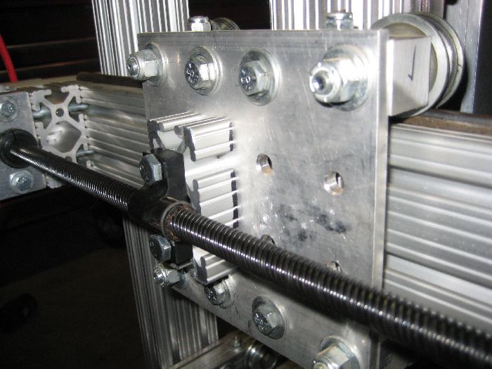
    Close up of the gantry's stepper motor setup:


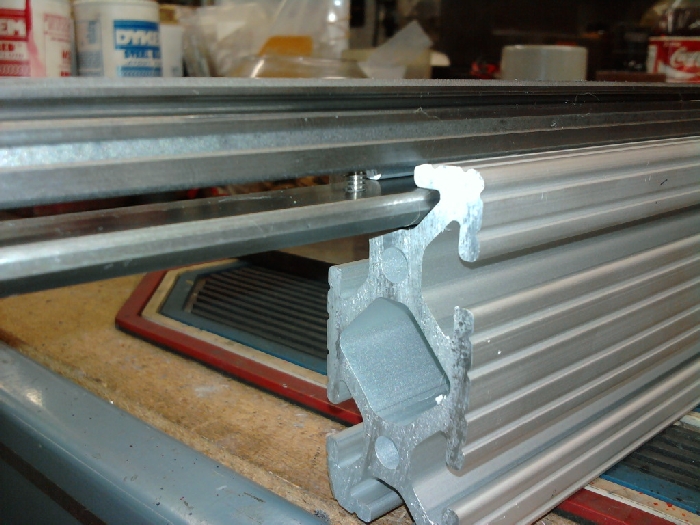
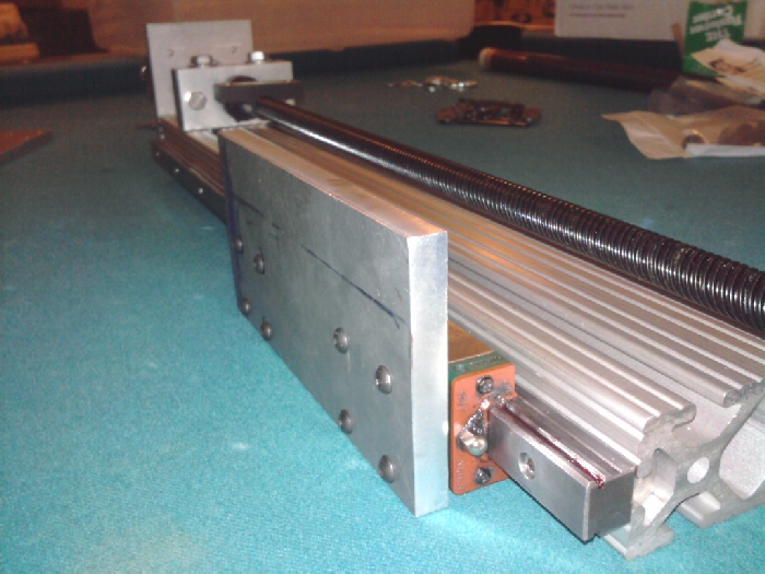
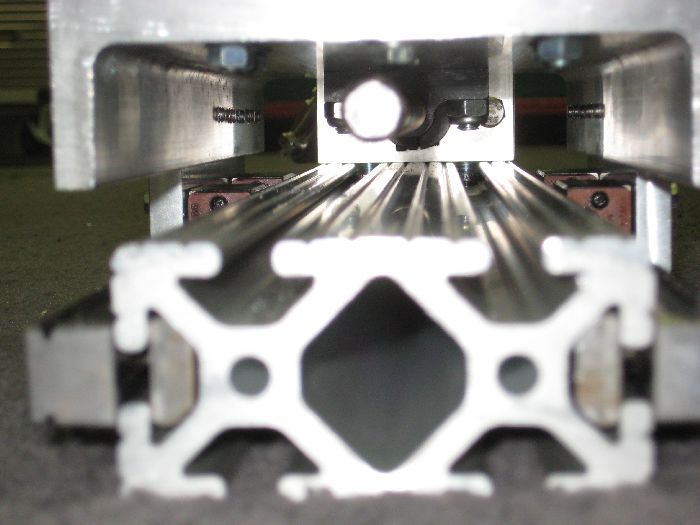
    The other side. The 2 bolts in the bearing block are 5" long bolts and go though the bearing block, spacer, horizontal beam and into the vertical beam to clamp everything together:


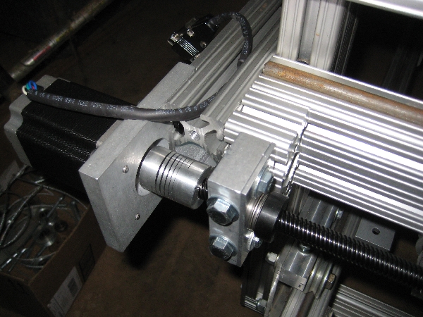
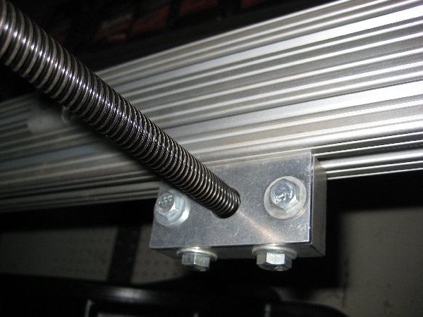
    The other bearing block on the gantry:


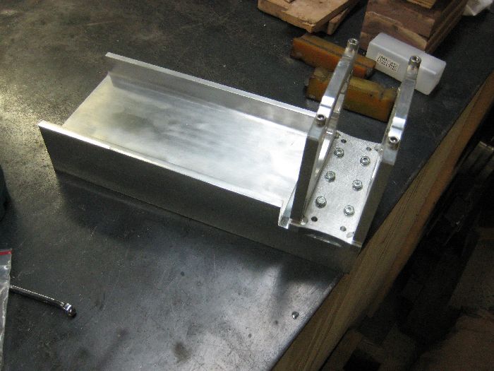
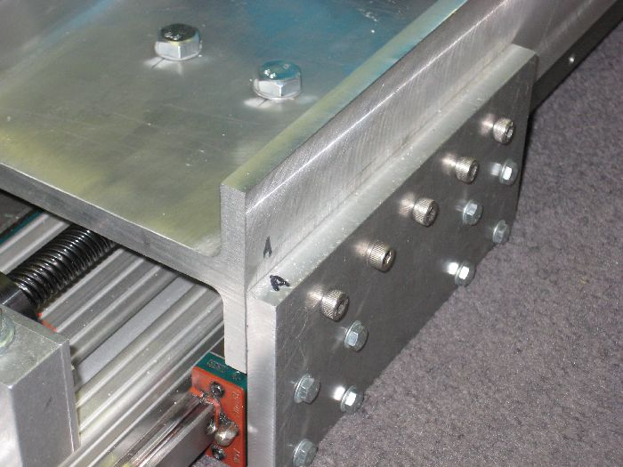
    Outside shot of the bearing block. Notice how the horizontal #1530 beam has 2 bolts going into the side of it plus the 2 bolts for the bearing block going though it. My logic is overkill is better. The gantry at this point weights right at 63lbs.


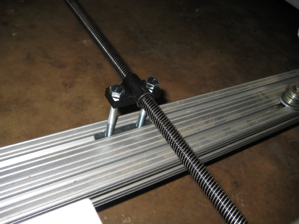
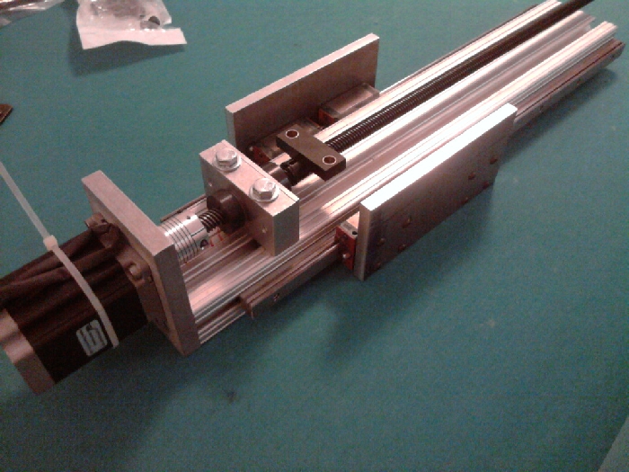
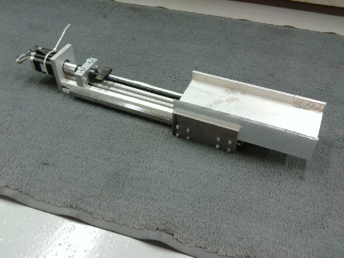
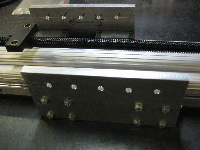
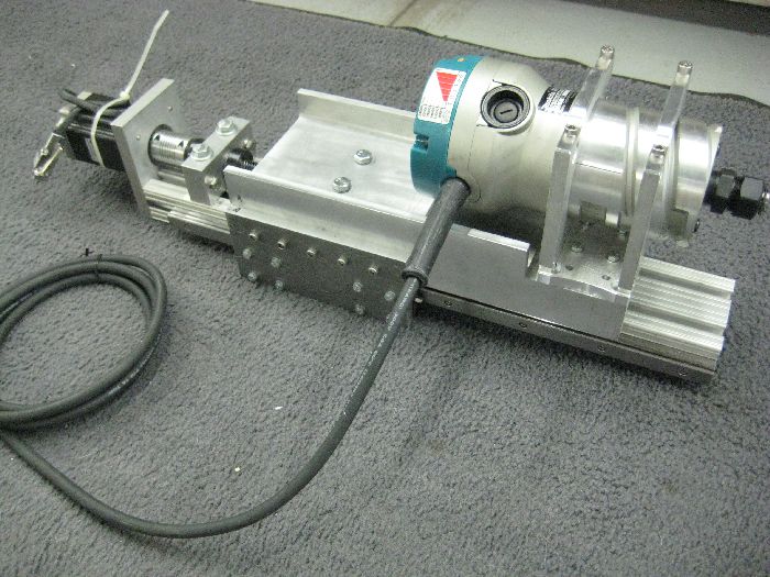
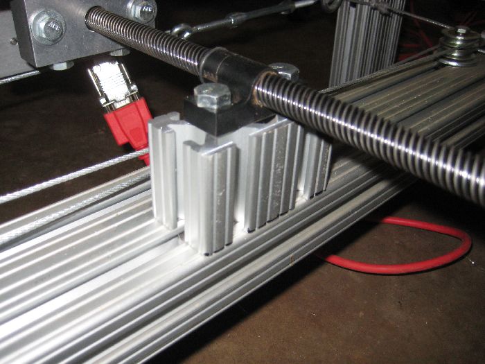
    Putting the stepper motor on the base was a lot easier to do:


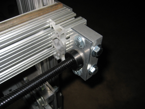
    Bearing block on other end of the base. I had to sand this Acme screw, the bearings would not slide over them freely, or really at all, maybe 2" then bind.


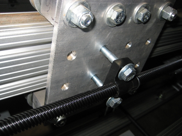
    For quick and dirty testing, I just tossed some bolts in, not secured at all:


    Gantry is the same way. I will be cutting some #1530 to make spacers for these so they can be secured down correctly.


    Decided I REALLY some action out of this thing, so I dragged out the computer and G540 (still very much hotwired up poorly for bench top testing) and rigged up the electronics real quick. Note the excitement of the dog:


    After a few minutes of poking around the software, I got this:

    [nomedia="http://www.youtube.com/watch?v=Su5H0LKoVj4"]YouTube- CNC first test run.[/nomedia]

    I know just enough about the ECM2 software to get what you see in the video to happen. Once I get the Acme nuts bolted down correctly, I can really start to dive into the software side of things. My goal is to draw a circle, have the start and end points meet. Ohhhhh ahhhhh.


  3. #23
    Member arizonavideo's Avatar
    Join Date
    May 2008
    Location
    USA
    Posts
    1185
    Downloads
    0
    Uploads
    0

    Default

    First movement is always fun. It's a bit of work to get this far.

    Is their backlash adjustment on the plastic nuts?


  4. #24
    Registered
    Join Date
    Apr 2008
    Location
    USA
    Posts
    235
    Downloads
    0
    Uploads
    0

    Default

    Looks good man - thanks for the video

    I wish I'd have gone with the beefier aluminum - yours looks like it will hold up really well but I've had to reinforce my Y axis with a steel plate because it was flexing / twisting (note my aluminum is only 30mmX60mm) here's a link to the couple of changes I've made recently HERE

    looks good though - can't wait to see it cutting!


  5. #25
    Registered
    Join Date
    Apr 2009
    Location
    USA
    Posts
    69
    Downloads
    0
    Uploads
    0

    Default Z Axis moving along!

    Getting some free time to work on the project again....

    For some time I had been pondering what kind of router to get. I figured I would end up with a cheap pawn shop special or something but I ended up getting a brand new Makita RF1101 for free! Problem solved.

    I scored some linear rails off eBay for $70 shipped that are in good shape. I ordered a 8020 Inc Standard T Nut Profile 15 S 8900 x 36 N, drilled and tapped for the linear rails:


    Slid the rails onto the 1.5" sides of a piece of 8020:


    To get the rails lined up, I laid the 8020 on a flat surface and put some drill bits under the linear rails, snugged the cap screws down just a little then tapped on the rails until they were resting on the drill bits and finished tightening down the cap screws.

    Made two plates, marked the holes for bolts to secure into the pillow blocks for the linear rails:


    One of 2 plates bolted up:


    A good overall shot of how things are going so far:


    Stepper motor, Nema 23 mounting plate, coupling, bearing block and 5 start acme nut were purchased from CNC Router Parts..

    I've purchased a mount for the router from K2 CNC:


    So I've got like 12 inches of travel on the Z axis but the problem is the router would need to extend beyond the bottom of the 8020 piece. But a flat plate might vibrate and cause issues. In a classic case of life isn't about what you know, but who you know, my friend that has helped me with this project dug up a piece of scrap aluminum I-beam. We decided to cut it down to 12" long:


    The base of the I-beam is much thicker than the top part, plus the vertical part of the "I" tapers a little. Also the base is wider on one side as well. We had to do some milling on it:


    Once that was done, we has to make the base thinner, so the real fun began with the super fly cutting:


    After fly cutting the base, we did a test fit:


    A near perfect fit. There is no hardware holding the I-beam in place, it is an smooth snug fit between the 2 plates. Now to make it so the K2 router mount can be fitted:


    And a test fit, again, no hardware holding the I-beam in place,just a good fit so far:


    The I-Beam needs to be drilled and tapped so it can be mounted up and secured in place. I need to make spacers for the X and Y axis acme nuts so I can bolt them in place as well. With that, I think I'm 90% of the way to being able to actually use this thing. I'm 5% of the way knowing how to use this thing.... help! No, really, any one in Knoxville know this kind of stuff?

    Hope to spend Sunday wrapping up the final loose ends, will update.


  6. #26
    Registered
    Join Date
    Apr 2009
    Location
    USA
    Posts
    69
    Downloads
    0
    Uploads
    0

    Default

    Spent a few hours on the project today and I dare say I'm 99.9% complete now!

    Had to drill 2 extra holes in my K2 bracket. Lined it up on the I-beam, transfer punched, center drill, then final drill the I-beam, bolt up bracket:


    I removed the 2 metal plates from the bearing blocks of the Z axis, marked where the bolt holes for the I-beam will be, dot punched them:


    Center drilled, final drilled them, bolted them back up to the bearing blocks:


    We found some metal strips to space the I-beam to the correct height. The strips were just laid on top of the bearing blocks, then while I pressed down on the I-beam, my friend used some small C clamps to secure everything in place, then used a transfer punch to make our marks:


    Center drill first, then we followed up with the final drilling:


    Tapping the holes in the I-beam:


    Cleaned out the tapped holes, and bolted the I-beam up to the Z axis. Lined up about as perfect as we could ever hope for:


    We marked the I-beam for 2 holes for the acme nut, center drilled, drilled and bolted it up. With great pride we present, a Z axis:


    After all that fun, the last task at hand was to mill some spacer blocks for the X and Y axis acme nuts. I took careful measurements and hoped for the best, we milled down some scrap 80/20 I had, drilled out the 2 bore holes and ended up what looks to be a perfect fit:


    I raised the cross beam up that the Z axis is mounted to, then dropped the Z axis into place, squared it up and torqued it down. Ladies and Gentlemen, I present to you.... my CNC mill (nick name "Bubbles"):


    Notice how my my AWETHUM dog is looking... AWETHUM as always:


    Quick video tour:

    [nomedia="http://www.youtube.com/watch?v=e2C4lKUwkSw"]YouTube - CNC Mill[/nomedia]


    I hope to score some cable guides out of a Chrysler mini van this week. But with this, I should be ready to start doing some mill work... assuming I can figure out how to use it.


  7. #27
    Member Khalid's Avatar
    Join Date
    Apr 2006
    Location
    Pakistan
    Posts
    3498
    Downloads
    0
    Uploads
    0

    Default

    Pencilneck
    wow wow and wow.. You are a smart man with lot of intelligence.. Thanks for sharing too many pictures with us.. I really appreciate you for using I-beam for your Z-axis..Great idea...

    http://free3dscans.blogspot.com/ http://my-woodcarving.blogspot.com/
    http://my-diysolarwind.blogspot.com/


  8. #28
    Registered
    Join Date
    Apr 2009
    Location
    USA
    Posts
    69
    Downloads
    0
    Uploads
    0

    Default

    Purchased a sheet of 3/4" MDF and at Home Depot the other day and had cut into 27.5" wide strips, so I have 3 bases now and a good scrap piece for more practice work. The L brackets that were mounted onto the base frame were for running screws though and securing the base plate.

    After a little messing around I found I could fit a nice 6" grid patter onto the base plate, 5 across, 8 rows. I drilled out the holes and mounted T-Nuts under it so that 1/4 X 20 bolts can be used to secure items into place.


    I was having some issues with my stepper motors making weird buzzing noises and not working. Part of the issue was the tiny pins used in the DB9 connectors were getting hot, burning up the pins (hot spotting) and then allowing the pins to get pushed back when plugged up:


    I ended up cutting the ends off and using some Molex connectors which has helped a lot, but not 100% fix my stepper motor issues.


    These plugs are also easier to unplug so I can get the cables out of the way when needed.

    I suspect part of my problem is the Gecko G540 is getting hot with use. If I unplug the power supply for a few minutes then plug back up, then things work fine for a short spell. I'm going to see if I can improve the cooling of the G540 and also dial back the voltage some.


  9. #29
    Member
    Join Date
    Apr 2007
    Location
    USA
    Posts
    8082
    Downloads
    0
    Uploads
    0

    Default

    I'm not surprised that the pins burned. I looked at the DB9 RS232 Standard specification and found no dc current rating per pin, but I know that these are rated as "signal pins" not "power pins". When I was doing backpanel designs for central office DSL systems and for telecom systems we would not rate them as high as 0.5amps. I have seen them rated in the 0.2amp range.

    Your motors are drawing peak DC currents many times that amount. What is needed is a connector with at least 5 amps dc rating per pin and is gold plated. Only a solid brass pin will deliver that in a small pin size. These pins are hollow rolled sheet brass or steel.

    Molex connectors of the type you used are tin plated. Though they can handle a little more current, they will oxidize and become unreliable with time.

    To avoid all of this I hard wire mine and just cut and splice the wires when necessary.

    CarveOne

    CarveOne
    http://www.carveonecncwoodcraft.com


  10. #30
    Registered
    Join Date
    Apr 2009
    Location
    USA
    Posts
    69
    Downloads
    0
    Uploads
    0

    Default

    Quote Originally Posted by CarveOne View Post
    I looked at the DB9 RS232 Standard specification and found no dc current rating per pin, but I know that these are rated as "signal pins" not "power pins".
    Indeed. And yet the G540 uses them. 
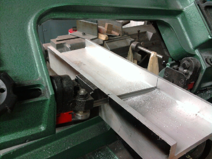
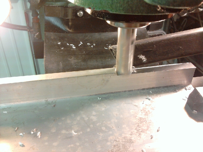
I've turned down my power supply to 40 volts from 48 volts and I did some cutting today.


    That took over 1 hour to mill out. I would blow compressed air on the underside of the G540 every so often to cool it off and didn't have any issues this time. I'm just going to get a cheap clip on 120V fan to blow on the bottom side of the G540 to keep it cool and I think that will be the end of most of my problems.

    Quote Originally Posted by CarveOne View Post
    Molex connectors of the type you used are tin plated. Though they can handle a little more current, they will oxidize and become unreliable with time.
    I'll put a dab of dielectric grease on them and that will protect keep them from oxidizing for a long time. Until I get the final set up for my mill (hope to be moving into a new home next month), I'm unplugging the cables and getting the computer cart out of the way.

    Toyed around a little more with clamping. I ended up finding some scrap 1X4 from a home office desk I built and cut several different size pieces, drilled holes into them and then drop the bolt though. There are T nuts under the work surface. Just snug the bolts down a little and the board isn't going anywhere. Not real pretty, but simple, cheap and works great.


    Playing around with this stuff, ended up spray painting that black, then sanded on it for a bit:


    Pretty pleased with the results so far. The only issue I have is the X axis is not parallel with the work surface, off just a little. It seems to only show on real fine detail though.


  11. #31
    Registered
    Join Date
    Apr 2008
    Location
    USA
    Posts
    235
    Downloads
    0
    Uploads
    0

    Default

    Hey man! everything's looking great - good job!

    You should "true" your MDF base then it would be perfectly parallel to your X axis - basically just run a big bit (biggest you can run) all across the whole surface - then it will be perfect


  12. #32
    Registered
    Join Date
    Mar 2010
    Location
    US
    Posts
    371
    Downloads
    0
    Uploads
    0

    Default

    Quote Originally Posted by CarveOne View Post
    I'm not surprised that the pins burned. I looked at the DB9 RS232 Standard specification and found no dc current rating per pin, but I know that these are rated as "signal pins" not "power pins". When I was doing backpanel designs for central office DSL systems and for telecom systems we would not rate them as high as 0.5amps. I have seen them rated in the 0.2amp range.

    ...

    CarveOne
    Ah, thread drift. I was thinking about that, as well as the gauge of wire used. What is your wire? The motors want 5A or so of current probably peaking a bit more. We should be looking at 18 gauge wire, and yet I suspect most folks are using 20 or even 22. It's also a distance thing. A couple inches of 20 ga is not so bad. 8' or 12' of it is not good.

    Ahren, are watching this thread? What is in your cables?


  13. #33
    Member
    Join Date
    Apr 2007
    Location
    USA
    Posts
    8082
    Downloads
    0
    Uploads
    0

    Default

    Quote Originally Posted by brtech View Post
    Ah, thread drift. I was thinking about that, as well as the gauge of wire used. What is your wire? The motors want 5A or so of current probably peaking a bit more. We should be looking at 18 gauge wire, and yet I suspect most folks are using 20 or even 22. It's also a distance thing. A couple inches of 20 ga is not so bad. 8' or 12' of it is not good.

    Ahren, are watching this thread? What is in your cables?
    The Gecko FAQ recommends 18AWG to 16AWG for step motors and 22AWG for other wiring. I was using 18awg unshielded automotive wire until I recently changed to four conductor 20AWG shielded cable. A volt or so of voltage drop in the longest cable (~19 feet) shouldn't be a problem for me.

    Wigitmaster recently posted this link to a wire gauge chart and online calculator (down below the chart) that will be of use.

    My concern is not with the cables as much as it is with the DB9 pins beginning to burn due to the small contact surface area, especially when the pins are not quite fully mated for one reason or another. The pins will get hot from higher than normal contact resistance, and start the frying or sizzling sound. By then the pins are dissolving from the heat and arcing.

    If this becomes a problem for other customers, there needs to be a solution in hand. Just choose a similar cost connector that is rated for DC power transmission. Wiring two DB9 connector pins for each motor wire would be a possibility, but I wouldn't really want to recommend doing that.

    Btw, Aston Martin makes a DB9, and I would love to keep a few of them around the shop for just in case I need them.

    CarveOne

    CarveOne
    http://www.carveonecncwoodcraft.com


  14. #34
    Registered
    Join Date
    Mar 2010
    Location
    US
    Posts
    371
    Downloads
    0
    Uploads
    0

    Default

    Hah, we are each not worried about the other's problem.

    The original ITT Cannon D sub with solder contacts is rated at 4.8A per contact.

    The D*U crimp contact is rated at 5 amps. The AMP equivalents are the same. Of course, some cheapie imitation may not be that good.


  15. #35
    Member
    Join Date
    Apr 2007
    Location
    USA
    Posts
    8082
    Downloads
    0
    Uploads
    0

    Default

    Quote Originally Posted by brtech View Post
    Hah, we are each not worried about the other's problem.

    The original ITT Cannon D sub with solder contacts is rated at 4.8A per contact.

    The D*U crimp contact is rated at 5 amps. The AMP equivalents are the same. Of course, some cheapie imitation may not be that good.
    That's good to know. Those are about right for a 3 amp motor if you factor in the usual engineering safety factor for power pins.

    The reason that we didn't consider the pins as power pins is that we felt that we had to assume the worst case for reliability (MTBF) calculations. Nowadays the situation is worse than it was back then. Reliability is not a predictable value after dumping the Incoming Inspection department and their statistical sampling test procedures, so now we may get anything that is cheap.

    One other thing I can think of in Pencilneck's situation is that the motor current is reversing polarity at a fairly high frequency. There may be some higher than normal current spikes during the polarity reversals due to inductive kickback in the motor coils. I doubt that even the ITT Cannon connectors could handle that for more than a short time if it is repetitive at a particular speed.

    CarveOne

    Last edited by CarveOne; 10-11-2010 at 07:15 PM.
    CarveOne
    http://www.carveonecncwoodcraft.com


  16. #36
    Registered bobsch's Avatar
    Join Date
    Oct 2008
    Location
    USA
    Posts
    406
    Downloads
    0
    Uploads
    0

    Default

    Quote Originally Posted by CarveOne View Post
    Btw, Aston Martin makes a DB9, and I would love to keep a few of them around the shop for just in case I need them.

    CarveOne
    Wouldn't we all.

    With that new router of yours, why not just make one?

    Bob

    "Bad decisions make good stories."


  17. #37
    Member
    Join Date
    Apr 2007
    Location
    USA
    Posts
    8082
    Downloads
    0
    Uploads
    0

    Default

    Quote Originally Posted by bobsch View Post
    Wouldn't we all.

    With that new router of yours, why not just make one?
    Powered by steppers or servos?

    I think I have about wound down on this thread. Turning control back over to the owner now...

    CarveOne

    CarveOne
    http://www.carveonecncwoodcraft.com


  18. #38
    Registered
    Join Date
    Apr 2009
    Location
    USA
    Posts
    69
    Downloads
    0
    Uploads
    0

    Default

    Here is a better photo of another one of the DB9 connectors that were on the stepper motors:


    This is actually a different one than the other photo, but you can see the pin pushed down and how the lower 4 pins have signs of hot spotting and the upper 5 look good. Don't know what the female connectors looks like inside before I cut them off and trashed them.

    Since crimping in the molex connectors, turning down my power supply's voltage from 48V to 40V and keeping the underside of my G540 cool with compressed air, the issues of stepper stutter has gone away.

    To permanently fix the G540 overheating issue, I will put a CPU heatsink and cooling fan that I'll pull from some old computer (free parts).


  19. #39
    Registered
    Join Date
    Mar 2010
    Location
    US
    Posts
    371
    Downloads
    0
    Uploads
    0

    Default

    I'm thinking you had a connector seating issue. The top pins engaged, the bottom ones didn't. One of them got pushed out of the connector (they are crimped on the wire as separate pins, and then the pins are inserted in the connector body). There was arcing on the bottom and not on the top.

    With DB series connectors, you really need to engage the lock mechanism (screws or latch), and make sure the connector shells are seated completely and stay that way.


  20. #40
    Member
    Join Date
    Apr 2007
    Location
    USA
    Posts
    8082
    Downloads
    0
    Uploads
    0

    Default

    The top row of pins are not aligned, and the second pin from the left looks like the hole is enlarged also. Can you find any markings on the metal body of the connector that indicates a vendor name?

    I'm in agreement with brtech.

    CarveOne

    CarveOne
    http://www.carveonecncwoodcraft.com


Page 2 of 3 FirstFirst 123 LastLast

Tags for this Thread

Posting Permissions

  • You may not post new threads
  • You may not post replies
  • You may not post attachments
  • You may not edit your posts
  •  


About CNCzone.com

    We are the largest and most active discussion forum for manufacturing industry. The site is 100% free to join and use, so join today!

Follow us on


Our Brands

8020 mill... long winded post, 56K killer.

8020 mill... long winded post, 56K killer.