New Machine Build CNC milling machine - 2nd attempt - Page 2


Page 2 of 3 FirstFirst 123 LastLast
Results 21 to 40 of 44

Thread: CNC milling machine - 2nd attempt

  1. #21
    Registered Drools's Avatar
    Join Date
    Feb 2009
    Location
    Canada
    Posts
    1290
    Downloads
    0
    Uploads
    0

    Default

    Hi Bob, I'm no expert so I'm not going to comment on the runout but I sure would like to see some pictures of the spindle and some details.
    Your runout question is better asked in the PCB milling forum.


  2. #22
    Registered bob^'s Avatar
    Join Date
    May 2006
    Location
    Australia
    Posts
    27
    Downloads
    0
    Uploads
    0

    Default

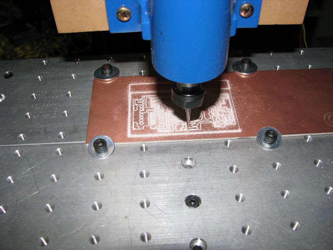
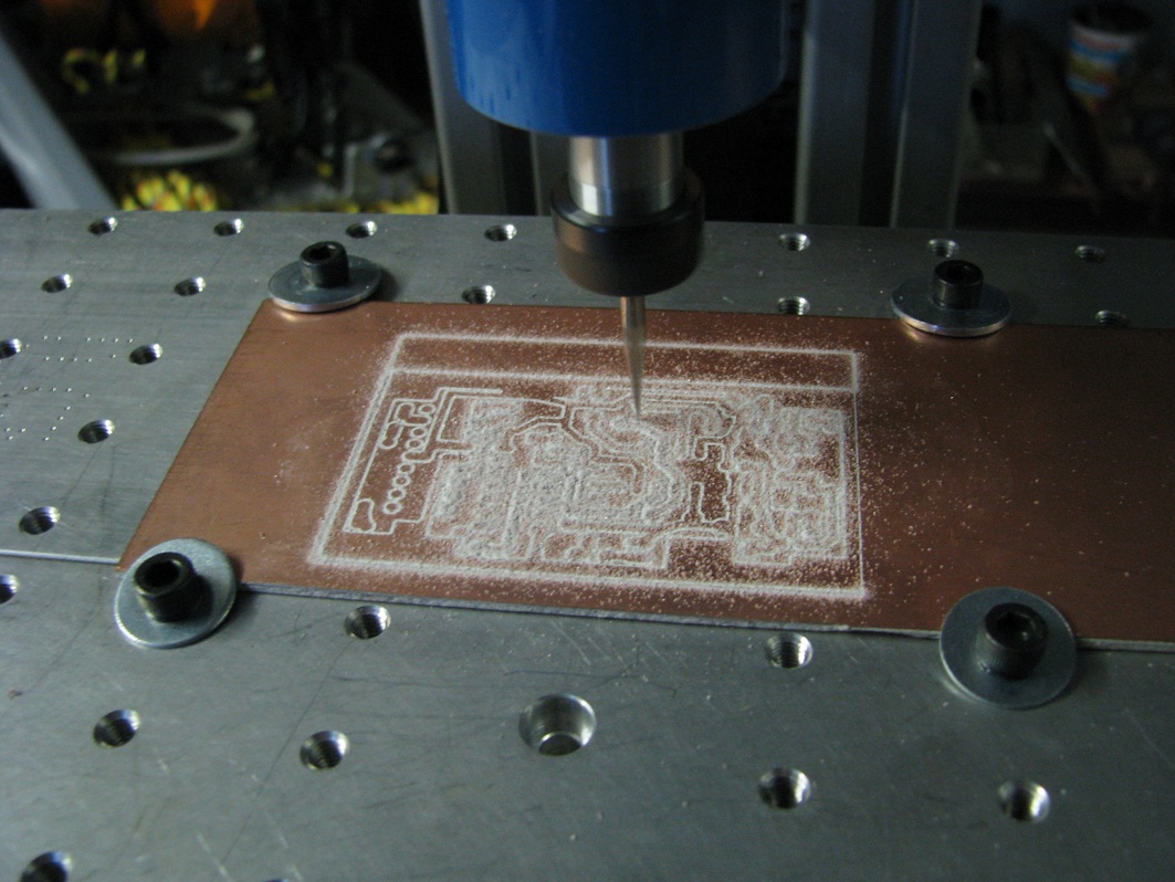
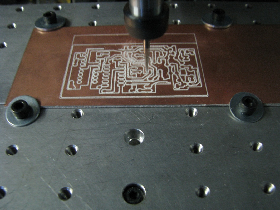
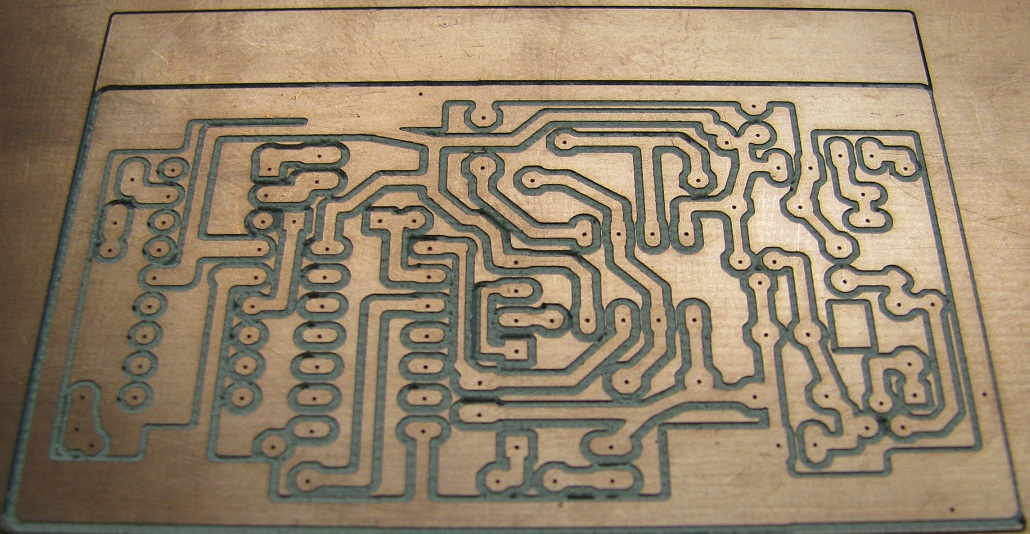
    Sure thing, I mounted it up today and gave it a test run. The finish is much much better than with the dremel - not a burr to be felt. The quality of the cut is also a lot better, the edges are better defined and more straight.
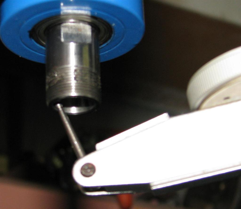
    I am using an old dremel knock off with 2mm of run out (no joke) to run the spindle just to see how it goes. I will be looking at buying a chinese water cooled spindle soon though.
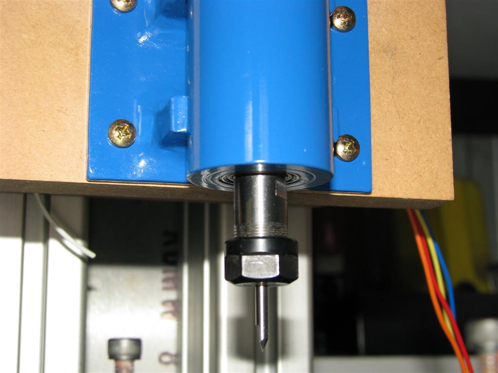
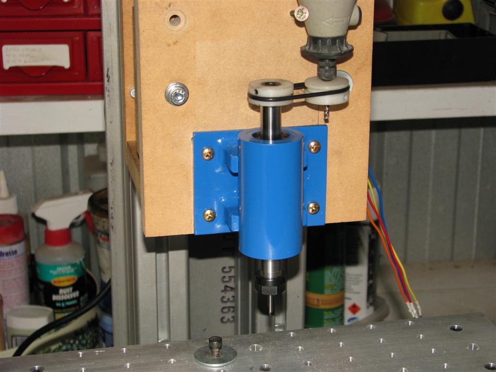
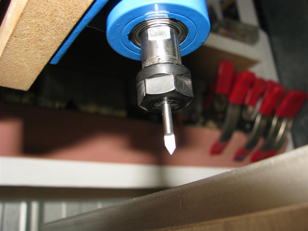
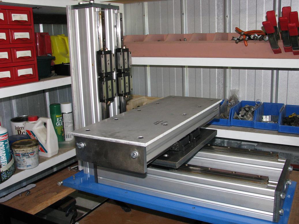
    Here are some pics (excuse the messy wires - everything is still temporary)


    Here is where the runout is coming from


  3. #23
    Registered Drools's Avatar
    Join Date
    Feb 2009
    Location
    Canada
    Posts
    1290
    Downloads
    0
    Uploads
    0

    Default

    Do you thinking making the end plates from 6061 Ali would make a big difference in the performance of the mill?


  4. #24
    Registered bob^'s Avatar
    Join Date
    May 2006
    Location
    Australia
    Posts
    27
    Downloads
    0
    Uploads
    0

    Default

    I couldn't tell you to be honest. I would assume you would have to go thicker, but I have not used any science in selecting my thicknesses for the mild steel.
    The one that needs the real strength is the plate mating the X and Z axis. But even then, I have 4 M8 bolts going from the bottom 16mm plate up into the extruded aluminium for the Z axis which are 90mm long.
    Then I have 4 M6 bolts with T nuts that hold the same aluminium, to the mild steel end plate.
    That end plate in turn is mounted to the extruded aluminium for the Z axis by another 4 M8 bolts which are also 90mm long.
    Overkill? possibly haha


  5. #25
    Registered
    Join Date
    Feb 2007
    Location
    Germany
    Posts
    24
    Downloads
    0
    Uploads
    0

    Default

    Hello,

    nice machine that you´ve build and a very nice spindle. Do do you have plans or sktches of the spindle?

    Greetings Rene


  6. #26
    Registered bob^'s Avatar
    Join Date
    May 2006
    Location
    Australia
    Posts
    27
    Downloads
    0
    Uploads
    0

    Default

    Hi Rene
    The spindle is pretty simple in design. It's only intended use is for PCB's so I only have one regular roller bearing at each end, with the ends machined to suit the bearings.
    Hope that helps.
    One problem I am having is that the bearings are getting quite warm. The bearings are 6801-zz and they are spinning under 30,000rpm which is in their specifications.


  7. #27
    Registered
    Join Date
    Sep 2008
    Location
    USA
    Posts
    111
    Downloads
    0
    Uploads
    0

    Default

    I was woundering about the bearings getting hot. i am in the process of designing my own spindle and I am stuck on cooling it. I thought about an internal fan with ports for exhausting but if I reverse the spindle it will create a suction. But after thinking some more I have decided when would I ever need to reverse spindle? so internal fan I will try.


  8. #28
    Registered bob^'s Avatar
    Join Date
    May 2006
    Location
    Australia
    Posts
    27
    Downloads
    0
    Uploads
    0

    Default

    Yeah I didn't think about cooling at all when I made it. I have thought about a couple of temporary fans situated at the top and bottom but it will play havoc with dust.


  9. #29
    Registered
    Join Date
    Feb 2007
    Location
    Germany
    Posts
    24
    Downloads
    0
    Uploads
    0

    Default

    hello bob^,

    with roller bearings i have made the expirience that when i had made the clearence to small then the temperature rised very soon.

    Greetings rene


  10. #30
    Registered
    Join Date
    Sep 2008
    Location
    USA
    Posts
    111
    Downloads
    0
    Uploads
    0

    Default

    Quote Originally Posted by bob^ View Post
    Yeah I didn't think about cooling at all when I made it. I have thought about a couple of temporary fans situated at the top and bottom but it will play havoc with dust.
    yes, the dust is my biggest fear. I don't want dust to get inside the spindle, so if you go with a single direction ONLY. I think you could get away with it, if it blows out rather than sucking the air in. Check your dremel. it has a rotary fan inside that blows exhaust out. same concept, I THINK


  11. #31
    Registered
    Join Date
    Jun 2005
    Location
    Australia
    Posts
    21
    Downloads
    0
    Uploads
    0

    Default

    Hi Bob^

    What run-out does you spindle have?


  12. #32
    Member
    Join Date
    Apr 2007
    Location
    USA
    Posts
    8082
    Downloads
    0
    Uploads
    0

    Default

    Quote Originally Posted by cad01 View Post
    yes, the dust is my biggest fear. I don't want dust to get inside the spindle, so if you go with a single direction ONLY. I think you could get away with it, if it blows out rather than sucking the air in. Check your dremel. it has a rotary fan inside that blows exhaust out. same concept, I THINK
    In order for air to blow outward, it has to come in from somewhere else. Otherwise there can be no airflow or cooling effects.

    For example, router motors exhaust air downward towards the cutter to help clear away the chips, to help cool the cutter, and that's where the dust is created. The fine dust that gets in at the top end of the router motor is just floating in the air.

    If the motor direction is reversed, the intake would be at the cutter end of the router motor and would immediately suck up all of the loose material that it can. Not good for the motor at all.

    The intake should be as far away from the source of the dust as possible. The only other thing that can be done to minimize dust intake is to add a filter to the intake that can provide enough air flow while filtering the air. That is simply not practical in many applications. Not impossible, just not practical.

    CarveOne

    CarveOne
    http://www.carveonecncwoodcraft.com


  13. #33
    Registered bob^'s Avatar
    Join Date
    May 2006
    Location
    Australia
    Posts
    27
    Downloads
    0
    Uploads
    0

    Default

    Quote Originally Posted by ghassall View Post
    Hi Bob^

    What run-out does you spindle have?
    Hi mate
    My spindle has 0.035mm of runout. The collet shank that I used was advertised to have 0.002 runout so I'm not exactly happy with it.
    I haven't tried milling a PCB with it yet, but I have engraved some aluminium and the finish was beautiful. With the dremel I had significant burring - that has now gone with the new spindle.


  14. #34
    Registered bob^'s Avatar
    Join Date
    May 2006
    Location
    Australia
    Posts
    27
    Downloads
    0
    Uploads
    0

    Default

    Tried out a PCB last night. It was the very first, and I probably should have tried with a smaller one as this one took at least half an hour. I know what I did wrong, and what settings to change to fix it, so the next one should be a lot quicker. I also went a little deep with this board.

    Here are some pics


  15. #35
    Registered Drools's Avatar
    Join Date
    Feb 2009
    Location
    Canada
    Posts
    1290
    Downloads
    0
    Uploads
    0

    Default

    very good, What bit did you use? Any changes in the spindle?


  16. #36
    Registered bob^'s Avatar
    Join Date
    May 2006
    Location
    Australia
    Posts
    27
    Downloads
    0
    Uploads
    0

    Default

    I used a 15 degree ( I think) engraving bit. No changes to the spindle - and it got awfully hot for the half hour or so it was running.
    But I am working on a new one now similar to one I had seen in another thread. It involved getting a brushless helicopter motor with an 8mm shaft, pressing the shaft out, and replacing it with a collet chuck with an 8mm shank.


  17. #37
    Registered metalworkz's Avatar
    Join Date
    Oct 2006
    Location
    Modesto, CA U.S.A.
    Posts
    975
    Downloads
    0
    Uploads
    0

    Default

    Hi Bob,
    I like the machine you have built and will be following your thread to see any further developments with it. Thanks for sharing the build with us!

    Regards,
    Wes


  18. #38
    Registered bob^'s Avatar
    Join Date
    May 2006
    Location
    Australia
    Posts
    27
    Downloads
    0
    Uploads
    0

    Default

    Time to bump this thread up.
    It has been a long time since I have touched my machine. I started building my own house in 2010 so that left no time for hobbies (or money!).
    Fast forward 3 years and I have my workshop set up, and my machine stripped to bits to rebuild as it had been sitting in my dad's shed for those 3 years under a cover and had developed some rust on the mild steel components.
    I have now cleaned it up, rebuilt it, and aligned my x and y linear rails a lot better (had a slight twist in the y axis which I managed to shim out, which was causing some binding)
    Here's where you guys come in - I am stuck on how to make a rigid z axis. I want the machine to have 100mm of travel so as to accommodate larger parts. I have two directions I can go here... Mount the linear rails direct to the 40x80 aluminium uprights and then have a z axis that mounts to that which will then come out 200mm so by the time I add a spindle, I should be around 240mm away from those uprights.
    The problem I see here is there is then a lot of counter weight (if that is the right word) on the rails affecting the rigidness.
    Like this:

    The other option I have is to get some more 40x80 to bolt to the front of those uprights, and then some 12mm aluminium plates bolted to the sides of these to join them together. On the face of this extension I mount another plate which the carriages for the linear rails will mount to. I then mount the linear rails onto the z axis itself.
    This would reduce that overhang from the spindle to the rails by about 100mm.
    I hope that makes sense, if not I will do a quick sketch.
    I also need to re-enforce those uprights as at the moment I am getting a little bit of flex out of it (.002-.003"). The way it mounts is 4 80mm long 8mm bolts which come from underneath the large steel plate, as well as 4 6mm bolts mounted to T Nuts at the rear of the bottom axis.
    The next step is to fill the uprights up with a granite epoxy to help add a bit of mass to the machine.


  19. #39
    Registered bob^'s Avatar
    Join Date
    May 2006
    Location
    Australia
    Posts
    27
    Downloads
    0
    Uploads
    0

    Default

    Here is how it looks at the moment. The ballscrew on the bottom axis is a temporary feature as I need the extra travel for a part my wife needs for the nursery. The things we do!
    The good thing is it gives me more time to work on the machine as the sooner it is done, the sooner she gets her parts.

    Attached Thumbnails Attached Thumbnails CNC milling machine - 2nd attempt-uploadfromtaptalk1371852385600-jpg  


  20. #40
    Registered bob^'s Avatar
    Join Date
    May 2006
    Location
    Australia
    Posts
    27
    Downloads
    0
    Uploads
    0

    Default

    My new workshop
    Just need to finish the doors and make up some more shadow boards.
    My wife doesn't understand why I tapped into to the house heating and cooling for in here also.


Page 2 of 3 FirstFirst 123 LastLast

Tags for this Thread

Posting Permissions

  • You may not post new threads
  • You may not post replies
  • You may not post attachments
  • You may not edit your posts
  •  


About CNCzone.com

    We are the largest and most active discussion forum for manufacturing industry. The site is 100% free to join and use, so join today!

Follow us on


Our Brands

CNC milling machine - 2nd attempt

CNC milling machine - 2nd attempt