
 Reply with Quote
could try some eccentric bushings to adjust for the slop. It looks really tight!


Tonight was a good night, I got my first linear bearing rolling on a track. I've kicked a few ideas around before I settled on this simple (I think it is simple) design. My goals here are something fairly cheap, easy for most people to copy and able to withstand 3 ton TNT blast at 10 yards. 2 out of 3 isn't bad.
The bearings are based on Geeksgonebad thread here.
So my starting point is a a piece of 8020 brand 15 series 4370 uncut. Uncut is the key here. I got them off the 8020 ebay store.
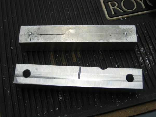
The first step was to cut the 4370 plates down to size. I simply bolted them together as such and made a score line down them.
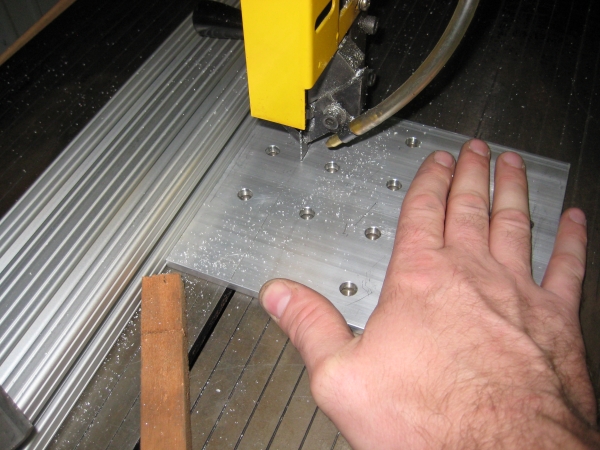
I clamped a piece of the extruded T-slot to the band saw, checked and double checked that I had it square to the blade and at the right location and made my cuts. I would use a piece of scrap steel to clean the blade every to often, just make small cuts into the steel would knock out the aluminum that was getting stuck to the blade, and it would cut faster.
My first 2 cuts and an uncut piece of 4370. You can see the score line on it. Simple stuff so far.
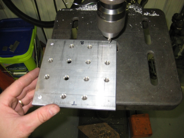
After a lot of measuring and basic math, then some carefully placed dot punches, I did some center drill points on the main body of the bearing plate.
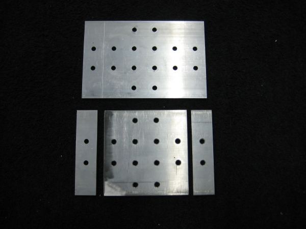
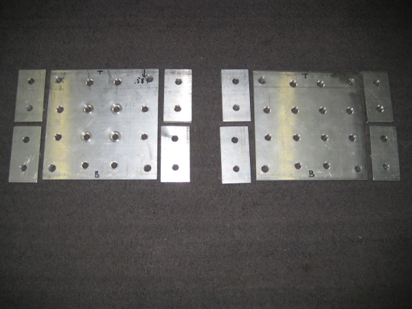
So here are the plates all cut up and drilled out. Took the thin strips, center punched the extra holes, drilled them out, and cut in half. The small 2 hole pieces will be used on the legs and upper section of the gantry. And you can see the 3/8" holes on the corners of the main body plates.
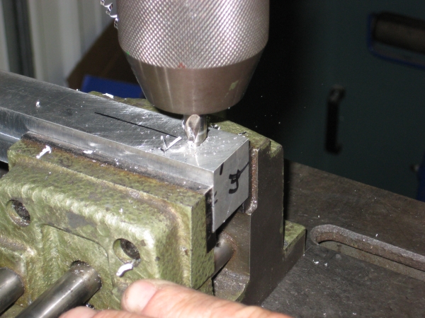
Onto the 1" stock bars or whatever they are called. Now here is where things were sort of cheated. A friend of mine went to get some 1" stock bar and said it turns out it isn't a very common size, so he milled down some scrap aluminum he had sitting around and made nice 1" bars, about 6" long. I lined them up with the holes I drilled into the main body, center punched and now center drilling them.
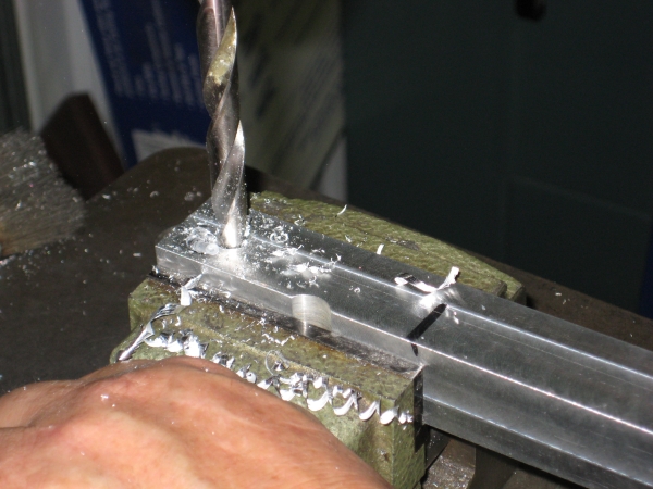
After center drilling, running the 3/8" drill though them and follow up with a little de-burning.
The 1" bars, upper one with the center drill points, the bottom one with the 3/8" holes drilled though. You can sort of see the center line scored across them as well.
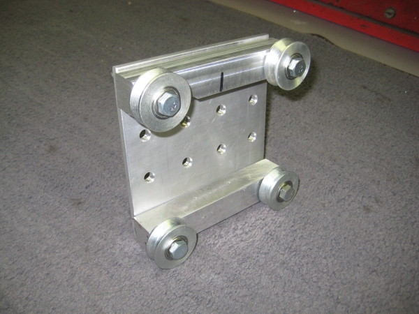
Now to bolt things together! Ohhh...ahhhh.
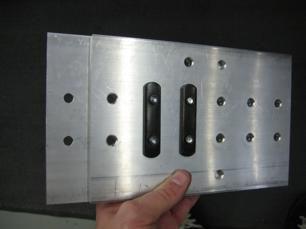
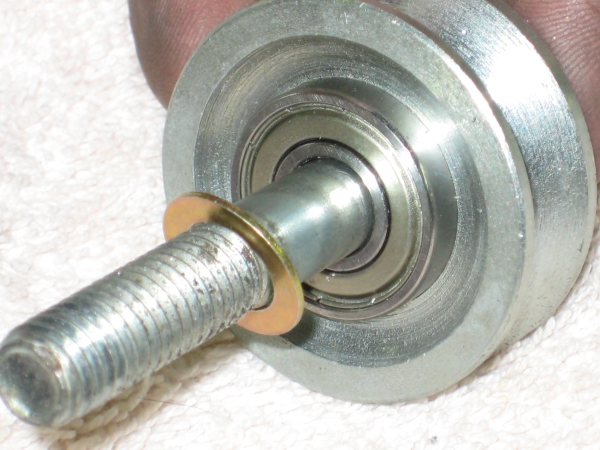
On the first fitting of the bearing asm, we found that the rollers were not rolling. The outer race was making contact with the 1" stock. I said something along the lines of "lets toss a small washer between the bearing the block", to which my friend digs up these magic special washers, forget what he called them, but they are very thin and are perfect.
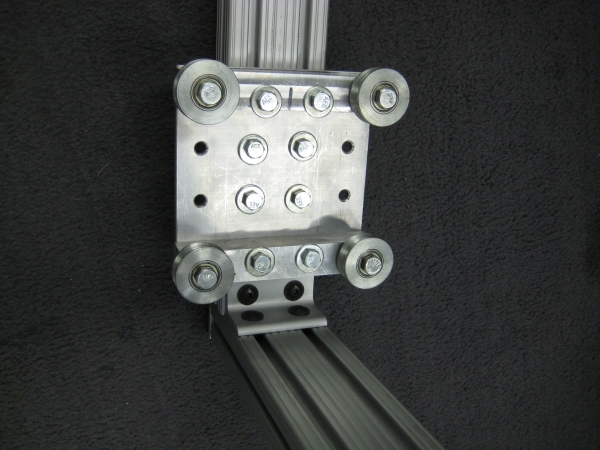
And the almost final product! It is not a perfect fit, there is a tiny bit of slop up and down, so I will be going back and slotting the holes for the bottom bearings and adding some tension screws or something to that effect. If I find the top bearings are out of alignment, I'll slot the holes there as well and make them adjustable. It rolls pretty smooth though.
There is still more work to be done, I've got to drill 2 holes each in the 1" stock that line up with the holes in the main body (the 4370 plate) so that bolts can go though it into the T slot. All 6 bolts holes down the middle of the plate will have bolts though it to the vertical arms of the gantry.
And for the quick and dirty video I made, where after reading my rambling, you can hear my rambling.
"http://www.youtube.com/watch?v=nR0o2I4qxAQ"]YouTube - MVI 0500
Feel free to rip off this design, truth be told that is sort of what I've done to get to this point.
Similar Threads:
could try some eccentric bushings to adjust for the slop. It looks really tight!
___________________________
http://jack.works
Looks great! that's going to be very good you can just tell!
I wish I had the shop and the guy with all the spare parts you have! hehe
Awesome - keep us posted!
You could use 2 pieces of threaded rod to pull the rollers together. Drill vertical holes top and bottom near rollers and run a rod on either side vertically. It would probably help support it too. Nice job BTW. What did you use for the bars on the top and bottom of the profile?
Brenidn
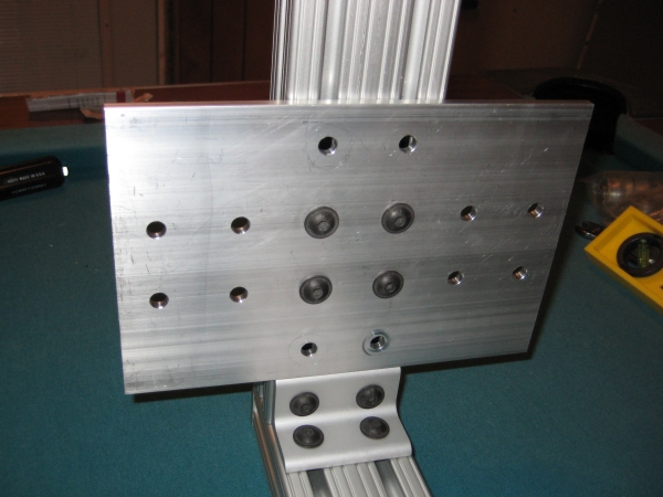
A little more done tonight... The 1" square bars, while bolted onto the 4370 plates with the bears, I center punched the back sides, unbolted everything and drilled 3/8" holes in them. This will allow for some wiggle room since 5/16" bolts are going though those holes, this photo shows that sort of mocked up.
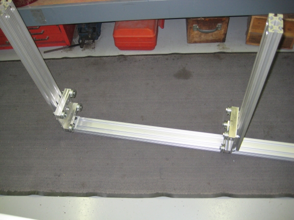
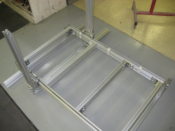
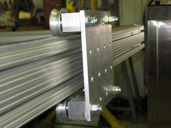
An overall shot of the gantry itself. I'm going to have to figure out how much of the bottom part of the T slot that goes off to the right to cut off.
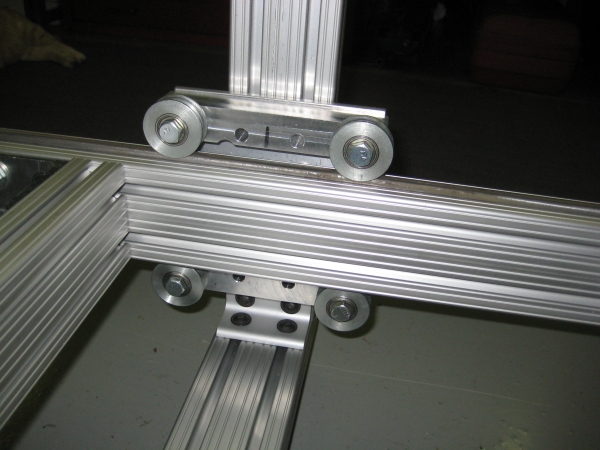
Another awethum view of the home made linear bearing. You can see the center 3/8" holes I drilled into the the 1" square stock bar. At the bottom of th assembly is a 4 hole corner bracket. The 4370 plate is butted directly against it. Should note I'm using the "machined edges" for the top and bottom of the 4370 plate, the edges I cut are to the left and right side. I'm hoping the machined edges will line things up better.
And an overview shot of what I've got so far. For now I've got 3/8" round rod for the "butcher bearings" to roll on, my friend that is helping me is pushing me to use drill rod, which is much nicer but jacks the cost up. My goal of a $1000 mill isn't going to happen as it stands already.
And since you don't get to see a cat with 6 toes very often, I've included this video that also a little bit of "action" with my progress so far.
"http://www.youtube.com/watch?v=y3Xs0iROt2U"]YouTube - Gantry
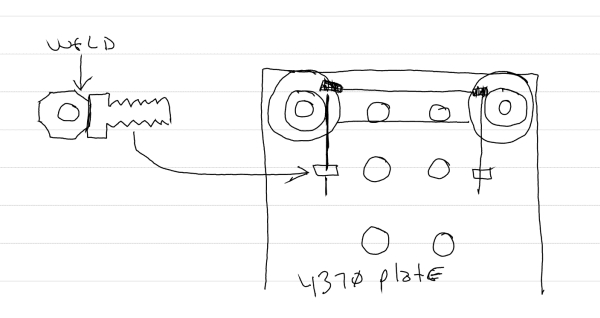
In the video I try to describe how I'm going to make the bearings adjustable... you'll notice what is in my "mind's eye" doesn't translate well in my ramblings. I will be drilling 2 holes, vertical, in each of the 1" square stocks. There will be bolts with a nut welded to the head of each bolt, then this special bolt will be bolted to the 4730 plate. A long bolt will pass though the vertical hole in the 1" square stock and thread into the welded nut. By tightening the long bolt, it will pull the bearings inward. The idea is to be able to dial in each bearing so I can fine tune the gantry's position in relation to the base. The extra part to do this will cost maybe $3.
Here is a quick and dirty drawing of how I hope make it where can fine-tune the gantry:
Last edited by pencilneck; 09-23-2009 at 11:01 PM.
looks 'the balls' , keep the updates coming
Check out some of my vids: http://www.youtube.com/user/blauschuh
It's a such a good feeling the first time you roll your gantry. I stood on my rollers and fell off, so your doing better than me. Nice job.
or you could use threaded rod like this...
I was going to say using threaded rod with nuts at each end seems like it would be a much more simple idea and keep the whole construction very simple and easy to do. I like this bearing though! Looks good.
Yea man, drill 4 holes and move on. That's my vote but it is your buildOriginally Posted by Xnaron

I'm wanting to be able to fine tune the adjustments of the bearings so the gantry can be dialed in to be level and squared with the base. After scribbling in my note pad for a couple of minutes, I think what you mention would work.
Drill the holes in the 1" square stock pieces, drop long bolts with a nylon insert nut. Loosen the lower bearings and pull them down as far as they will go, then tighten them back up. Loosen the upper bearings and then start to tighten the long bolts and dial in the gantry, then tighten the upper bearings locking them into place. Loosen lower bearings again and start to tighten the the long bolts until the lower bearings are snug so that there is no free play, tighten the lower bearings down.
I'm going to run with that first, 4 long bolts should still keep that cost under $3. Will be a few days before I can do this.... will post updates once completed.
Thanks for the input.
Thats pretty much how I did it too - I figured if things loosened up I could just tighten the bolts
Not sure if you can see that from these pictures - I'm planning on taking a bunch of close up pictures this weekend
Yeah that picture is very heard to see lol.
hehe Sorry about that
Here's a few better pictures
Can I ask you what size are those holes in the slotted metal you got and where did you get them? The ones I've seen the holes were larger than 8mm but yours looks like a perfect fit.
I shop at Lowe's for nearly everything
I'm not sure of the exact size of the holes and I'm at work and can't run out and measurebut I do know that I had to drill the holes just a bit because they were just a hair too small for the bolts - I want to say I am using a 3/4" bit and 3/4" bolts? but I can double check that when I get home tonight
5/16 (8mm) is the fit for regular skate bearings. What bearing size are you guys useing?
Product Description: 1606-ZZ
BORE .3750, OD .9063, WIDTH .312
From Here - These are slightly larger than regular skate bearings
Oh and I checked the dimensions and I'm using 3/8" drill and bolts
Same here as well, the 1606ZZ bearings, running 3/8" bolts though them.
For now, the 4 holes in the 4370 plates that I drilled are 3/8", but will be going back and enlarging them to 13/32" to allow for adjustment so I can level the gantry.
I cut the bottom piece for the gantry last night, will have to use some shims so that the vertical arms of the gantry will be parallel. Once I do that, I'll start a new build thread with more hot-N-sassy photos.
Also starting to look at how I can use my wife's old desktop computer to house the power supply and G540 for the stepper motors.
Thanks for the inner diameter info. It has stopped a lot of head scratching.
 Posting Permissions