Reply with Quote
Nice work, I REALLY like the way that looks.


After a couple of false starts I have finally settled on a design I am happy with, I was going to build a 4 metre long table but unfortunately the boat has to live in the shed as well so the router has to be somewhat smaller. Last time I started from the bottom up but this time I am starting from the top down, so here is what I have come up with for the Z axis, aluminium box is 75mm by 6 that I got a friend to mill out a slot and drill some holes.
The ballscrew just fits inside which is a bonus, it just needs a small plate underneath to give clearance over the corner radius of the box section. The slot is for the ballnut to attach to the spindle plate, I have the linear rail blocks made that the plate will attach to, you can see them in the photo's, I just have to cut out the plate, it will probably be cut from 100mm flat bar, and bolt to the bearing blocks I have made.
The plan is to do exactly the same for the Y axis and similiar with the X, for the X it will have the ballscrew on one side, kinda like those cantilevered designs, I have a friend that has done similiar with a bigger machine and it works fine so I am going with that idea.
I have a few ideas to try with this machine, PCB milling is high on the list and I am designing a 4 spindle attachment to put on, it is easier than a toolchanger and hopefully will work out, I am going to try it out.
For the standard spindle I am going to use a three phase spindle and VFD - funds allowing.
I have my own servo drive design based on the Elm Chan high power design that I am going to test out on this machine as the new firmware that has been done on the drive hasn't been trialled on a ballscrew machine as far as I know, if it works then I am going to post board layout's and parts lists for those that want a cheap intro into servo's.
Phase two for the drives is to bypass the step/dir side of the input and control the PWM scheme directly from EMC, taking encoders to the controller. The advantage of going DIY on the electronics is that I can build in some connectors that will allow me to just plug and play while I am changing the control of the servo drives.
Any hoo, enough of my rant, here are some photo's
Cheers.
Russell.
Similar Threads:
Nice work, I REALLY like the way that looks.
Hi Russell,
Good to see your machine started.
Very neatly done so far.
cheers,
Rod
Perth, Western Australia
Cheers guys, I forgot to mention a few other things, the servo is going to be direct coupled to the ballscrew, normally servo's have reduction pulleys but this one is way bigger than it needs to be, it is a 200W servo, the encoder was smashed in transit so I am going to use one of my spare's, I have a couple of the Digikey capacitive encoders left, I am using them on my first machine and they work very well. They have selectable resolution, up to 2048 CPR, so if I use the highest setting, this will give me 2048 times 4 (for quadrature) which is 8192 pulses per revolution, this is equivalent to 8192 steps per revolution with a stepper, so the resolution should be ok even direct coupling the servo.
This servo also has a brake, with 24 volts applied to the brake wiring the servo is free to spin, remove that voltage and the brake locks the rotor, it can still be spun with some force but it holds well enough to stop the axis coming down under gravity.
I have servo's for the remaining axis's, I have Electrocraft E543's, unfortunately they are a 60volt servo and the big blue one on the Z axis is 24 volt so I will need seperate motor supplies.
Ballscrews and linear rails for the rest are in transit so it will be a waiting game until they turn up, I hope to use the same approach but cannot buy any more box section until I know what size the ballnut's are to make sure they fit inside the box section...
Next is to finish off the Z and then I will go to work on the drivers, that should keep me busy until I get more parts in the mail
Cheers.
Russell.
Spent the afternoon/night organizing the shed so all the parts are now sitting on a nice clean table, I like to at least start off nice and neat, good intentions and all that
At least it is all off the dining room table, as they say : happy wife - happy life
While I am waiting on the rest of the parts I am thinking of getting the smallest BLDC RC plane motor I can find and testing the runout on it, I need rpm's about 30000 mark with as small a motor as I can, since I will be using four of 'em.
The plan is to use four linear rails, one block each with one spindle each, they will be "actuated" with solenoids, the lowest one doing the cutting and the Z doing its thing. There will have to be some offsets but this is the easiest way I can think of without using four servo's and four ballscrews, apart from being more expensive it would simply be too bulky. If I could get tiny ballscrews then it may be viable as servo's and drives are easy enough, especially really tiny ones, but it would still be crowded.
Will have to do some research on that one, I would dearly love a toolchanger but to get one that will do 30000 rpm and hold a 1/8th bit is not likely to happen.
Cheers.
Russell.


Russel, our machine at work has two routers that are activated with air cylinders. One ballscrew for the entire head, but the router's are raised and lowered with individual air cylinders.
Gerry
UCCNC 2017 Screenset
[URL]http://www.thecncwoodworker.com/2017.html[/URL]
Mach3 2010 Screenset
[URL]http://www.thecncwoodworker.com/2010.html[/URL]
JointCAM - CNC Dovetails & Box Joints
[URL]http://www.g-forcecnc.com/jointcam.html[/URL]
(Note: The opinions expressed in this post are my own and are not necessarily those of CNCzone and its management)
Hi Gerry, I thought about using air as it would give me a bit more travel, but then I need to have a compressor running and air lines, not the end of the world but I just thought that solenoids would do the same thing and it only really needs to travel the thickness of a PCB. I think either will work just as well it is just getting spindles small enough that is going to be really tricky.
Cheers.
Russell.
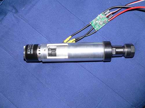
Not directly relevant to your application, perhaps, but I've built a small spindle using a 350 watt RC motor (the motor is rated at 550 watts, but I'm under-running it).
It's not had anything other than test use yet, but seems pretty good. One problem is finding a controller that will give a good start if the cutter is loaded and one that will stay in sync under changing load. The first (very cheap) Chinese controller I tried got very hot and didn't start well if there was even a tiny load on the motor. The second one was complete overkill (100 A!) but works very well and hardly gets warm. It was only about $40, so not too expensive, either.
Here's a pic, with the original cheap controller:
The spindle is just 38mm in overall diameter and uses ER16 collets. Max RPM is 16,000 on the 12V supply I have, but I could take it up to about 20,000 RPM (bearing limited) with a higher voltage supply.
I've done a fair bit of playing about with RC motors now and they are certainly good value for money. Controllers seem to be the limiting factor, as good ones are pricy.
Jeremy
Hey Jeremy, that is pretty close to what I had in mind, when you say 20,000rpm is the bearing limit do you mean the motor or the spindle ? I had heard some of these things (motor's) spin up to around the 40,000 mark.
My thinking was to make an intereference fit sleeve that goes directly onto the motor shaft with a thread that suits something like a dremel chuck, I just don't know how much runout these things have, they are cheap enough so I was just going to buy one and check it out.
The cutting load is minimal for this, cutting 0.2mm deep into copper and drilling 0.8mm and 1.0mm hole through PCB's shouldn't really strain the motor too much, I hope
Still having a proper spindle with collet chuck like you have pictured is very nice, where did you get the spindle ? Or did you build the complete thing from scratch ?
Cheers.
Russell.
Hi Russell,
The bearing limit is for the big bearings I have supporting the chuck. I decided to use a standard ER16 collet chuck and this came with a 20mm ground hollow shaft. I've used fairly big bearings to support this, but the highest speed ones I could find in this size (without going to insanely expensive ceramic ones) were limited to 20,000 rpm.
I opted not to use the motor shaft, mainly because it's only 5mm diameter and probably not up to taking much in the way of side loads. The standard bearings in these motors are supposedly able to take very high rpm, although there seems to be a fair bit of chat on some of the RC model forums about replacing the cheap Chinese bearings they are usually fitted with and going for something a bit better. Apparently bearing failure is reasonably common in big models that put a lot of load on the motor.
I've got around the potential bearing runout problem on the motor by coupling it to the collet chuck using a rubber dog coupling. This was easy enough to do and I can be sure that the motor bearings aren't seeing any side loads. You can just see the coupling inside the slot in the case.
If you were to go for one of the really big RC motors, then you get the benefit of a bigger shaft that you might well be able to use directly. I bought a couple of 2.8kW RC motors that have 8mm shafts, they were pretty cheap for the power, around $50 each. Probably overkill for a small spindle, but they can always be under-run for reliability.
Using an off-the-shelf ER type collet chuck means I don't have to worry about concentricity, plus I get a good range of collet sizes, from around 1mm diameter to maybe 10mm diameter. I'm currently probably only going to use the 3-4mm collet and perhaps the 6 to 7mm collet, as these will hold 1/8" and 1/4" cutters, which is all I really need.
The spindle came from a local tool shop, but they are often on eBay. Do a search on ER16 collet chuck and you should find a few. They aren't too pricy, either, I think mine was around £20 (maybe $30 US or so).
Jeremy
Yup that looks like it may be worth a look, I can go a smaller collet chuck as well, this may help get bearings easier (cheaper) for 30,000 rpm, there are ER11 chucks on Ebay, I am sure I have seen or heard of ER8 chucks as well, may check it out. The bits I will be using are only 1/8th shank so the smaller the chuck the better.
Thanks again.
Russell.
This one: http://tinyurl.com/aty49d looks to be a pretty good bet. It's cheap enough, plus only has a 12mm diameter shaft, so smaller, higher speed rated, bearings could be used. I've not seen anything smaller than ER11, but would guess that this would be about ideal for use with 1/8" shank cutters.
I had a real problem finding suitable thin section bearings for my spindle, like you, I wanted to keep the outside diameter down and with a 20mm chuck shaft this was a bit of a challenge. Looking at that small ER11 chuck I'm tempted to get one and build another spindle, because it looks to be a better bet than the one I have.
Perhaps best if I finish one machine first though, before building parts for another..........
Jeremy
Nah... where is the fun in thatOriginally Posted by Jeremy Harris

The ER11 looks like it may be the winner so far, 8mm shaft should allow for some small bearings.
Cheers.
Russell.
It looks like my remaining parts are in the country, getting a bit exciting now
With a bit of luck I will have them some time next week so I can work out what size aluminium to get for the remaining axis's.
I hope to finish the Z this weekend...weather permitting and I will connect up a spare drive to the servo and give it a trial run, I need to fit an encoder but that should not take too long.
Rod, since you are following this thread I have a question for you...do I need to have easy access to the servo/ballscrew coupling ? My current plan is to have it tucked away out of reach of dust/chips inside the box section as you see in the photo's, it will have to be joined to the servo, then the whole lot fed in and the ballscrew thrust bearing assembly bolted into place. This means the coupling cannot be accessed without removing the servo and ballscrew again. I assume with everything working correctly this will be a good thing to keep gunk out of the coupling and ballscrew bearings, but if I have to I can mill out a slot to gain access.
Any thoughts ?
Also weather permitting I may try to mill out some cable chain on the red beast, it has moved to the shed and I need to connect up the PC etc so that will be a good test run, I have some 3mm HDPE that should work well.
Russell.
Hi Russell,
The coupling is a no maintenance item so I don't see a problem with tucking it inside the box section. Obviously make sure the coupling is tight on the shafts as I know of a few missed steps caused by couplings slipping.
cheers,
Rod
Perth, Western Australia
Thanks Rod, I was hoping you would say that, I am trying very hard to cover the mechanical's on this build and that would help a lot. Any tips on suppliers ? I used hose clamps and air hose on the last one, was thinking of improving on that a little ... lol
Cheers.
Russell.
I prefer helical couplings to the other types and Peter Homann has them now. A plug for an Aussie supplierbut Peter is a good bloke and helps people a lot.
http://homanndesigns.com/store/index...7dba69580317a1
cheers,
Rod
Perth, Western Australia
Thanks Rod, I will check them out, I remember Peter from last years BBQ and he certainly is a helpful bloke.
Russell.
Didn't get as much done on the Z axis over the weekend as I would have liked, but managed to get a few things done.
I recieved a nice little parcel in the mail today, the remaining two ballscrews and 2 pairs of linear rails, also a smaller rail with four blocks that hopefully will form the basis for the 4 spindle head attachment to mill PCB's.
The ballscrews are one metre and 600mm in length and the rails are about the same so the final travel of the machine will be about 150mm on the Z, 800mm on the X and 400 on the Y, I will lose a bit of travel by spreading the bearing blocks but that is a neccesary evil.
Of course for those of you thinking "where are the photo's ?" here it is, quality isn't the best but it will have to do
Russell.
Well some brainstorming was done today along with a beer or two and between my friend Chich and myself the decision was made to have a crack at making a toolchanger for this beast, I won't go into any details just yet but I think that a toolchanger will make life so much easier, even if it only has space for four tools.
The approach is going to be as simple as we can make it so if it works it may help others out as well. The biggest problem faced is holding and releasing the tool so that is getting worked on first, I still think this will be better than making a four headed spindle attachment, at least for now...
Russell.