


 Reply with Quote
Your table looks amazing!


Here we go again....
I am adhering to the adage that people generally end up building more than one CNC. Once bitten by the bug there is no turning back...
For the last couple years, I have been tinkering with the design of a bent steel and aluminum CNC. This method of construction is something I have become pretty familiar with at my day job. I finally settled on the production model and began ordering parts last month.
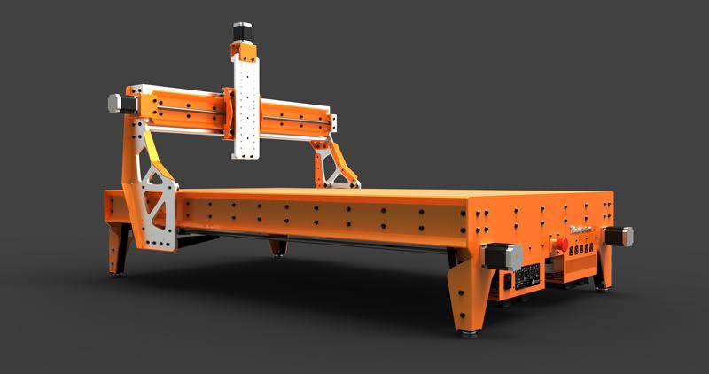
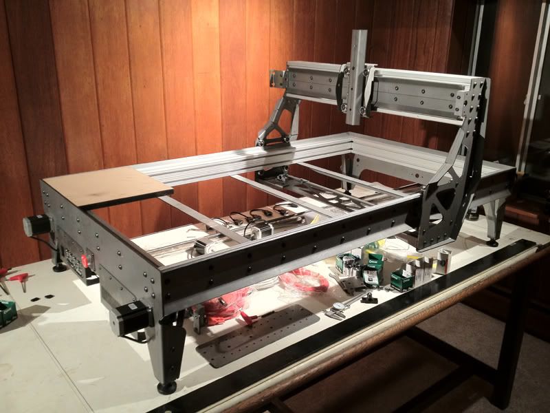
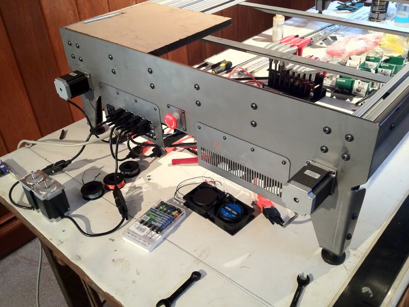
Here you can see the overall design of the machine. I am hoping to get everything powder coated once the initial build is complete.
I designed the machine with these options in mind: Mill, Plasma, Laser, Extrude, and Tangential Knife. I wanted to be able to pursue these functions at a later date. There is embedded in the design, allowance for a vacuum table or a water tank.
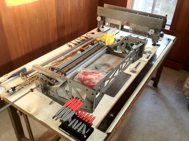
Once I received the steel, I quickly started assembling and test fitting. I had received a small batch of steel a few months ago so that I knew that the design for my linear motion would work before committing a huge amount of $. I also made a wrench for easy adjustment of the V-groove wheels.
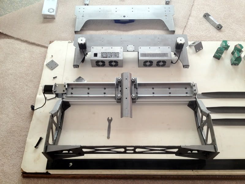
A friend gave me a huge old drafting table. After these pictures, I assembled my work surface so that I wouldn't wear out the knees on my pants. Here you can see that I am waiting on a shipment of 80/20 pieces. I had the cross member for a couple years now. I tapped all of the holes and assembled as much as I could.
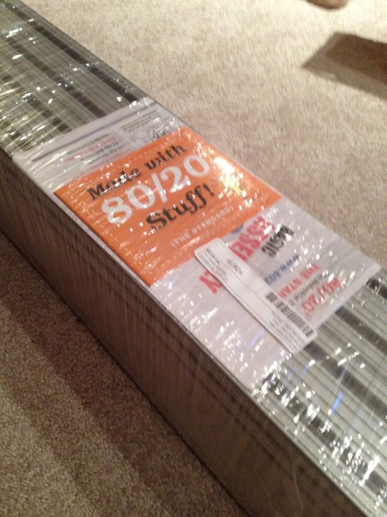
Whoo-hoo 80/20! Cut to size with all of the holes tapped.
Picture taken about 15 minutes after getting the 80/20
Footprint is approximately 3'X5'
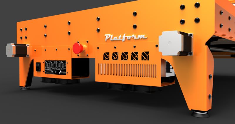
I am starting to rethink having the G540 in the front. Although it is a nice idea to showcase the $300 part, the logistics of routing the cables back under the table has convinced me to get these parts redone and mount it in the back of this 'saddle bag'
I began shopping for a craigslist computer, as I knew I wanted to leave my other MDF machine intact since the milling area is larger. I also felt it was time to get a flatscreen monitor. I found a great deal on a Dell XPS 400 circa 2006 with a 20” monitor.
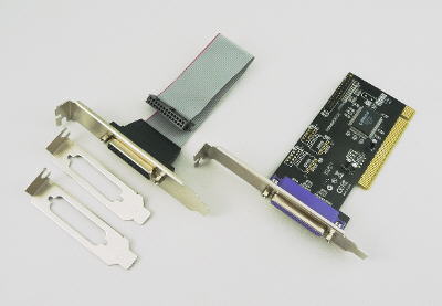
I got it home and noticed it was lacking a printer port. Oops. Well not a problem, right? I'll head over to Microcenter and pick one up. Not necessarily the case. If you find yourself in this situation, save yourself the headache I went through and buy a Rosewill RC-304 2 port PCI card. Even though other cards list EPP mode, your computer will automatically select ECP mode. Since the add on card is not part of your motherboard, you cannot control this. This card works and is made to work with the G540! My charge pump is on and everything works flawlessly so far.
PMDX.COM - Products for CNC and motion control applications
Finally, here is a short video showing the linear motion as the table sits now...
I look forward to any comments!!!
Brian Oltrogge
www.grunblau.com
Similar Threads:
Your table looks amazing!
A lot of thinking went into planning, well done beautiful machine
Nice I like it! Are you thinking about offering steel kits?
My CRP 48 x 48 build [URL=]http://www.cnczone.com/forums/open_source_cnc_machine_designs/144173-crp_4x4.html[/URL]
Great design and look. I had the same idea for the 45 degree metal for rails. can't wait to see how they work without having to actually do it. LOL
www.digitalPimple.com
Fyi, I found pins 1 and 17 on the Rosewill RC304 can't source enough current to drive the G540 reliably. They only source 1mA on mine, compared to 8.2mA on the other pins. The G540 requires 5mA, I believe. I made up a custom cable to use pins from both ports on the RC304 to drive all the inputs on the G540. This was causing me a lot of intermittent problems that I had a hard time tracking down until I broke out the o'scope and took a look at what was going on.
How did you get your steel parts cut (plasma, laser, ...)? Do you know what the pricing was on the cutting above the cost of the steel? I ask as I'm looking at getting that kind of work done on my next machine, but I haven't made it to the stage where I can send out drawings for quotes yet.
CNC mill build thread: http://www.cnczone.com/forums/vertical_mill_lathe_project_log/110305-gantry_mill.html
Vey nice design. I think some kind of support will have to be placed for the cutting bed if the spoil board will be wood but I'm sure you've taken that into account.
I'm very interesting to know if this type of build would cost less that a pure 80/20 build.
That looks awesome! great work so far...
Bravo... A few months ago I saw a post that said you were working on something different for your next build, they were not joking. Very nice indeed.
I'm curious what the deflection is like at the center of the Y axis. Also where can we order some of these parts from?
Thank you very much for the comments!
I'll have to look into the low current issue on the Rosewill card. Like I said “works flawlessly so far” (there is always something) Was the one you got from PMDX? Apparently they customize the board for the G540. I know you can buy the standard Rosewill card for like $15 at newegg... Unfortunately I don't have an oscilloscope, what issues should I look out for?Originally Posted by jsheerin

I won't have a solid idea of the cost until I am done getting all of the parts. Used to be you could figure on spending about double the cost of the steel, provided it wasn't insanely complex. So if your project uses $200 worth of steel, plan on spending $400 for cutting and steel cost. Doing multiples is also hugely beneficial to cost. There is a programming charge embedded in the first run of parts. If you can make parts the same, do it and just ask for multiples. For the gantry uprights I could have provided cadwork that shows two mirrored pieces. But considering there really is no difference from the top and bottom of a lasercut piece of steel, I just got two copies.
If there is enough interest, I will try to see if I can sell a couple locally first.
Thank you, it was a big risk going ahead with this design, I knew it 'should' work. I actually had three different fabrication companies produce test pieces. One of the companies completely missed the mark. They were using an old press brake, probably from the 60's but with the tonnage and 10' length. The other company has a brand new CNC Trumpf press break and were incredibly precise but with only 72" capability. I also split the rails down the center so that I could make minor adjustments as needed.
BTW- I think I purchased the V-groove wheels from you awhile back...
Yup, the bed configuration would have to change with function.
That is a good question, 80/20, although wonderful, is incredibly expensive. Mostly, I didn't want my build to look like an erector set of aluminum extrusions even though the 'bones' are 80/20. Since much of the strength comes from the 3/16" steel, I was able to skimp a bit on aluminum using it mostly for fixturing.
Yeah, Ger21 was the only person outside of family that saw any of my initial concepts... He is great at keeping secrets, lol.
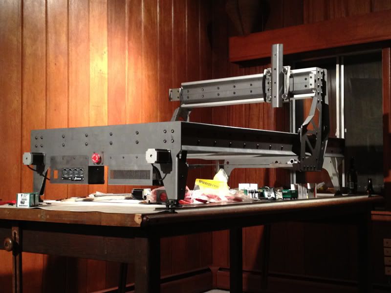
Not noticing any deflection in the y-axis. I'll go stand in it and get back to you.I could also switch these out to 3030 extrusion if needed (based on the hole pattern)
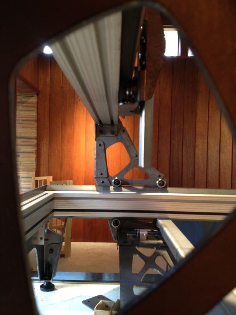
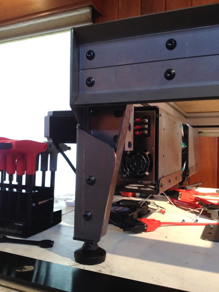
Here is another view through the upright. These steel pieces are meant to be place holders while I source a place to get some 3/8” aluminum waterjet cut. Cutting down on weight while upping the bling factor.
I also wanted to thank those who took me up on my offer of the $40 MDF3790 plan sets! I would have never been able to continue the R&D without your help!
Brian Oltrogge
Grünblau Design Studio
I bought mine from Newegg. I've got two of them now - they're great. I initially had problems with the printer port on a motherboard. It worked most of the time, but every once in a while (sometimes 6 months apart) the z axis would lose steps, sometimes catastrophically for a part. But then I wouldn't be able to duplicate it. Turned out it was due to low current capability, so the voltages going to the G540 were not in spec. I managed to reproduce it finally by running the axis very, very slowly. Then I broke out the scope - what I should have done to start with.
On the Rosewill card, which I bought to fix the above issue, I initially found that all the motion worked great. I measured the voltage drop from one of the card's pins to see how much current it could source, and it looked fine. Then I tried whatever is hooked to either pin 1 or 17 - I think it's one of the relay control lines which I had turning on my spindle. It didn't work right. That led me to check more of the pins for current capacity. I forget if I checked them all, but I noted that 1 and 17 were really low, so I made a cable using db25 connectors from Radio Shack to use the 'good' pins from both ports on the Rosewill card. Problem solved.
If the card's been modified, maybe that issue is fixed. You could check it by connecting an appropriate resistor from the pin you're testing to one of the ground pins and measuring the voltage drop across it with a DC voltmeter. Size the resistor to provide >5mA of current flow at ~5V, so for example, a 630 ohm 1/8 watt (or higher power) resistor would work (7.9mA at 5V, 6.3mA at 4V). You'll also have to use Mach to set the pin high (to 5V). If the voltage drop goes way down and thus current capability is low (less than 5mA), I would not use that pin with the G540 to avoid problems.
Thanks for the cutting cost info.
CNC mill build thread: http://www.cnczone.com/forums/vertical_mill_lathe_project_log/110305-gantry_mill.html
Update and Video...
I decided to go ahead and commit to moving the G540 to the back of the controller saddle bag. What a difference as far as ease of cable management (I still need to work up a permanent solution).
Here are the new parts...
The simple angles might end up living in the corners of the 80/20. Unfortunately, I do not have any drop-in T-nuts. So unless I get really ambitious and disassemble half of the build in order to install these corners, they will have to wait until after the powdercoater/painter (I don't know if I have the tolerances for PC). I also eliminated the extra fans in the power supply saddle bag these were entirely unnessesary as the integrated fan moves almost enough air to cool the G540.
Keep in mind this is only the initial fabrication mockup (think American Choppers), the rusty, uncoated steel will be finished and the thin steel uprights, Z plate, and lower cross-member will be exchanged for 3/8” aluminum. I had no real idea of the benefit of this until I started looking at the numbers.
I could be wrong, but this is what I came up with...
Steel ~ 0.29 lbs per cu in
Aluminum ~ 0.095 lbs per cu in
78 cu inches of steel @ 3/16” thick
=22.62 lbs for steel
156 cu inches of Aluminum @ 3/8” thick
=14.82 lbs for aluminum
Thats a weight savings of almost 8 lbs, 2/3 of what it is now.
What about strength?
For a plate in bending, the strength of the plate is related to the cube of the thickness. Aluminum being about 1/3 the density of steel can be at a 9 times advantage based on thickness at the the same weight. This offsets the 1/3 aluminum lacks in strength.
A simple rule of thumb:
Aluminum needs to be 1.5X times as thick as steel to have the same strength.
The aluminum plate at 2X the thickness would be over 2.5X stiffer than the steel at 2/3 the mass!
The bling factor has not been quantified.
Here you can see the rear facing G540 installed.
Compared with the front mounted one...
An issue I ran into was with the locking collars on the Z axis. You can see in this picture, the differences in the manufacturing tolerances from collar to collar...
Luckily, I ordered too many of these so I was able discard the ones that were made while the QC guy was on his break. Even with the more centered hole, I only have about 1/16” of clearance for these and had to exchanged the fastener with a button head.
I will likely have to alter the Z-axis linear motion plate to account for this in the future.
When I started this build I wanted to meet or exceed the capabilities of the Rockler Shark Pro...
Based on good and bad reviews of the Shark Pro CNC, I decided to try to use the cost of the Rockler machine as a sort of starting point for constructing a DIY machine. Using the $3500 cost point as a guide, I began designing, but I quickly abandoned the specs of the Shark Pro as they are not that useful to me. I will likely come back to it as an interesting comparison at a later date.
On Sunday, I was able to get everything assembled and configure Mach3. This video is the first test of the motion system. I ran a toolpath @ 200 IPM. I still have some minor tweeking and tuning of the G540. I wanted to be sure to be able to run at this speed at least as there are some materials that like to be cut between 100-200 IPM. I also have to figure out a more permanent solution for a cable carrier. As far as screw whip, it isn't a factor at this speed. I am also slightly tensioning the screws, so a full 6' McMaster span is definitely possible. I would not want to see what the 108” span of my MDF machine would do though.
That's it for now!
I still need to:
Figure out what and how I am going to mount to the Z-plate (hole spacing was based on K2 mounts)
Cut off the lead screws
Order the aluminum
Set up limit and home switches,
Manage cables
Build table surface
Buy Ger21's super slick Mach3 Interface
Brian Oltrogge
www.grunblau.com
Looking good. Are you using a single or multi-start screw? I hope it's a 5-start screw because this machine looks like it could take anything you throw at it.
Thank you, I am using Ahren's brand new Dumpster Nuts 5 Start lead nuts and screws.
love the video. looking great!
www.digitalPimple.com
I love this concept. I think the kits avaliable today are too much extruded. I think using bent steel is a great option that can potentially lower cost and increase ease of assembly and rigidity. The only downside I can see is you limit your table size choices.
Hope it works out and you can produce kits.
Why oh why can't we get this sort of terrific gear in OZ?
What a fantastic build Brian!
cheers,
Ian
It's a state of mind!
Looks great. Just curious what CAD software you used for your design, impressive modelling skills!
Thank you, I use Rhino3d for modeling, Keyshot for rendering, and RhinoCAM for toolpaths.
very nice!!! keep watching the progress
![Grunblau (Rustbelt) Platform CNC [build log]](https://www.cnczone.com/forums/images/cnczone.png)