

 Reply with Quote
I have a 900vac APC case that I was going to use for my G540 and my steel channel machine when I get around to the electronics part of the build. You beat me to it.
I like your choice of colors and paint work. Looks nice. Will follow along.
CarveOne


I'm another proud new owner of one of John's (microcarve) microCarve A4 machines. I'm using it with a Gecko G540 motor driver, 48V linear power supply, and KL23H276-30-8B motors purchased from Keling.
The items from Keling arrived last Tuesday, the A4 came on Thursday. Everything arrived in great shape. The packing job John did on the A4 was superb. The painted boards were wrapped in tissue paper, the table slide was in its own inner box marked "Don't Drop!"
I set up an old PC with EMC2 last week, it'll be the dedicated controller for the system. I considered mounting the power supply and Gecko inside the PC's cabinet, but since I'm not familiar with what sort of heat I'd get off the power supply and Gecko I decided to put them into their own case.
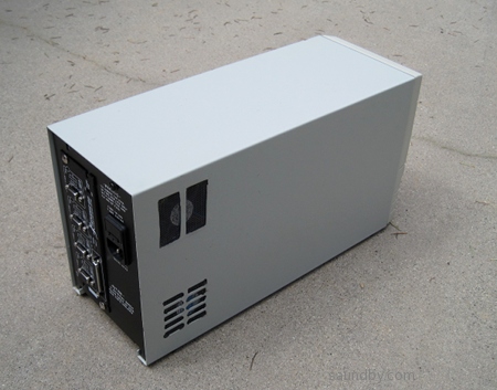
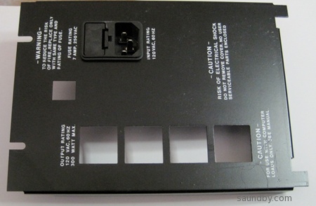
I decided to re-purpose an old UPS case I had hanging around in case it was ever needed:
I decided to mount the Gecko into the back panel in place of the holes for the prior power plugs:
At this point I'm doing the wiring of the power supply, cooling fans, and the Gecko. Once that's done, I'll be checking out the computer + Gecko, then hooking up the motors.
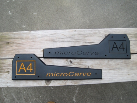
When I'm taking a break, I'm personalizing the A4 a bit. Here's a sort of "before and after" shot of the side boards of my A4 showing what I do when I'm not in the shop:
You can see more detail about what I'm up to with the build (like shopping for nibblers) at my blog:
An Infinite Number of Cats on Keyboards
and I'm on the microCarve Yahoo! Group.
Enough posting for me...now back to work!
Similar Threads:
http://saundby.com/cnc --my website
http://catsonkeyboards.blogspot.com/ --my blog
I have a 900vac APC case that I was going to use for my G540 and my steel channel machine when I get around to the electronics part of the build. You beat me to it.
I like your choice of colors and paint work. Looks nice. Will follow along.
CarveOne
CarveOne
http://www.carveonecncwoodcraft.com
Hey John, I just upoaded a new video for my Write2CAD program.Originally Posted by CarveOne

Show how to make a G540 Panel for cnc.
[nomedia="http://www.youtube.com/watch?v=lE9r_kKeZV4"]YouTube - G540panel.mp4[/nomedia]
Bob
CNC Projects
Nice job with the Gecko case and the paint!...
Thanks!
More progress today:
Airflow cutouts for the power supply. I wasn't worrying about cosmetics here, just getting it "good enough". Airflow is my biggest concern with this case.
I chopped the front off the original PCB to use the switch, a nice big red one. I left enough PCB to allow it to be secure in the original mounting hardware. It turned out that the switch could handle the AC current of the power supply, so I didn't have to use it to pull a relay or something. So I just cut the traces to the switch on the PCB then soldered the AC line wire to one of the N.O. contacts and ran a wire to the power supply's line input from the other contact.
First power-up of the DC power supply. Everything's looking good at this point. I wanted to put in a power indicator LED. So I put a resistor divider/current limiter on the DC output. I made it for 10mA at 6VDC on a 48V source. This was a bit anemic for the bicolor LED that was already on the PCB, so I wired in a red LED that's daylight visible at 10mA and hot glued it in the old LED's place. It sits perfectly behind the light pipe in the front panel and looks great.
The divider. The different colors of spade lug are on purpose. The bright one goes on the high side, the dark one on the low side. I put a thick layer of conformal coat over the exposed wires and a piece of shrink wrap over the top half after I took this picture. My conformal coat was Shelly Hansen's "Hard As Nails" clear, BTW.
Tomorrow I'll finish by getting the fans mounted, then I'll start testing the Gecko and the motors.
THEN, I'll start assembling the A4 itself.
The long form of what I did today, with more pics, is up on my blog:
MicroCarve A4 CNC Build Progress
http://saundby.com/cnc --my website
http://catsonkeyboards.blogspot.com/ --my blog
Nice! On the current limit divider what resistors would you use to make it 3 volts at 25ma?
Thanks
Starting with 48V, we'd need to divide that by 16 to get 3V.
For 25mA, we'd want 48/.025=1920 ohms on the high side.
1920/(16-1)=128 ohms on the low side.
In real resistors I'd use a 1.8K ohm on the high side, 120 ohm on the low side. This'll give you 3V at 26.7mA.
Check my numbers, or build one and measure it. I'm pretty bushed right now, but now you know the process to figure it out.
Note that the current is what will flow through a dead short on the low end of the resistor divider. A properly installed LED will show some resistance, which will vary by the LED. If it's not bright enough, keep the 15:1 ratio between the high and low resistances and move to lower value resistors. E.g. you'll get up to 32mA with 1.5K and 100 ohm resistors with a dead short across the low end (shunting the 100 ohm resistor). A bit less current will flow with an LED in the circuit.
My process is to figure out close values in my head, grab whatever is close to the top of the parts drawer for resistors in that range, hook them up to the bench supply with microjumpers, and see what I get with the multimeter, testing both voltage from ground to the union of the resistors, and current when placing the meter across the lower resistor in current measurement mode. Then I clip in a representative LED, if I'm smart. If I'm not, I make the divider cable, put it in, get disappointed because the LED isn't bright enough, then decide whether to replace the LED or the divider cable.
Last edited by saundby; 04-05-2011 at 01:42 AM.
http://saundby.com/cnc --my website
http://catsonkeyboards.blogspot.com/ --my blog
I got power to the Gecko today.
I changed my mind on the fan setup I'd planned yesterday. I decided to have two fans on one side of the enclosure blowing in, two on the other side blowing out. I also checked the airflow on the various fans I have around and determined that the larger CPU-style fans blow a lot more than the smaller fans (something like 70mm vs 50mm, I haven't taken a rule to them.)
So I cut two more fan ports into the case, put the mesh back over it all, installed the fans, wired them up and tested them. Then I put a connector on the fans and put a mating connector on the power supply.
Finally, I fit the whole thing together, wrangling wires and doing some trimming to accommodate the fans.
Then I led the power supply wires for the Gecko out of the hole cut in the back for the Gecko (I removed the Gecko after the test-fit, didn't want to take a chance of damaging it), hooked them up to the Gecko, plugged in and hit the power switch.
It worked fine. I got power and fault lights on the Gecko (no E-Stop installed yet, just power.)
Time to hit the sack now, tomorrow I'll mount up the Gecko, jumper the E-Stop until I've actually got a switch for it, and continue testing. Maybe even start assembly on the A4, but that's starting to look like Wednesday. *sigh*
At some future point I'll have to open this enclosure back up and tear down a bit again to cut the holes for the E-stop switch connector and the limit switches connector in the back panel.
Pics tomorrow.
http://saundby.com/cnc --my website
http://catsonkeyboards.blogspot.com/ --my blog
Thanks for the info!
Started wiring the motors today.
I have some Belden 8424 OJ cable (4 conductor with shield, 20ga.) recovered from another project some years ago. It's been unused until now because of crud crusted on it. I washed it up, measured it, and cut the first length, prepped it & went through my resistors to select ones for the motor current resistors for the cables, & drew up a wiring diagram for myself so that I have a guide and know what I've done later.
Then time ran short.
Looking forward to spinning a motor, and more, tomorrow. Thu & Fri are when I have the most time, usually.
http://saundby.com/cnc --my website
http://catsonkeyboards.blogspot.com/ --my blog
I used the resistors you suggested and I have a perfect 3 volts. The resistors get a little warm is that normal? I am only using 1/8 watt, that's what I had on hand. Thanks for the help!
1/8 watt should be enough, if you're getting 27mA at 3V, that's 0.081 watts, compared to 1/8 watt which is .125 watts. Still, you may want to measure your current at the high end and middle of the divider to see how close you are to the limit. For the current measurement at the top of the divider (between the 48V supply and the 1.8K resistor) multiply 48V times your measurement to get the watts there. At the middle, short it with the ammeter and then multiply that by your 3V to check the power at that point in the circuit.
It's sort of belt-and-suspenders (or belt-and-bracers, if you prefer) to check at both points, but that's the kinda guy I am.
http://saundby.com/cnc --my website
http://catsonkeyboards.blogspot.com/ --my blog
I've got all three motors wired and checked out now. EMC2 is happily driving them through the Gecko G540 on my bench top. All the currents and temperatures look normal for motors running with no load.
Now to start assembling the microCarve A4 itself. Hurray!
My promised pics got delayed by my daughter borrowing my camera. I've got it back now. The battery is dead, of course. It's on the charger.
I'll be getting some pics up later.
For now, more building, less posting.
http://saundby.com/cnc --my website
http://catsonkeyboards.blogspot.com/ --my blog
Thanks saundby for the help. I came up with .048 watts. I ran it for awhile tonight and everything seems fine. Like I said thanks againg for the help. Nice looking telescope by the way!
Thanks! It's been a great scope. For about 10 years now I've been showing people the sky through that scope. Literally more than a thousand people a year get to see various astronomical objects through that scope, each year since I built it.
Glad to hear the current is plenty low!
http://saundby.com/cnc --my website
http://catsonkeyboards.blogspot.com/ --my blog
Things went really well today. I've done a first pass at assembly on my A4, I'm sure some tweaks will be needed, but everything is together now.
Tomorrow I'll be hooking up the controller and computer and do some testing without a spindle attached. Once I feel like I've got the barest clue that I'm running things properly, I'll see about getting a spindle attached. Which will involve me constructing a mount for it, but otherwise everything will be ready.
The pics:
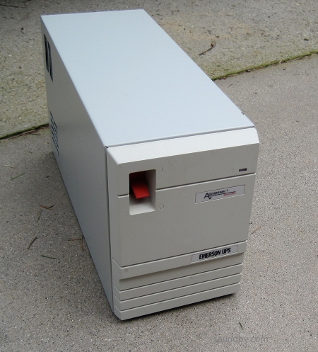
Here's the back of the controller box, as completed. The fan cutouts are where some small airflow slots used to be. The bottom one was my first go, the upper one is a later better version. If I decide I need more airflow after I've had the motors running under load, I'll cut out the crossbars on the lower cutout later.
The front, looking just like it did originally. I'm going to put some custom stickers over the Emerson ones later. For now, I've got a big red switch that goes "ker-chunk" and an LED power light.
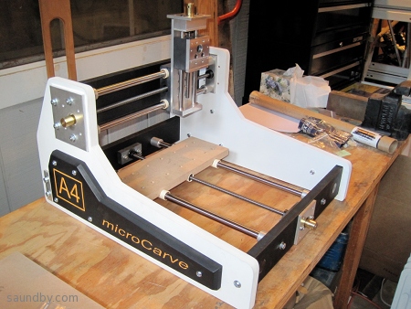
Here's the microCarve A4 fully assembled without motors. Later, I'll be posting a step by step guide with the assembly procedure I hit on as probably the best (on my third try.It wasn't much trouble, though. I was expecting to sort of feel my way through the process and it was fun.)
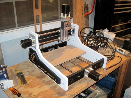
Here it is with motors mounted. I managed to steal a little time after dinner before an evening with the family to get this far. Tomorrow I'll bring the motor controller and computer out to the garage and start spinning leadscrews!
-Mark
http://saundby.com/cnc --my website
http://catsonkeyboards.blogspot.com/ --my blog
Well, I'm just Amazed at how good everything looks!
Beautiful work!
Thanks Very Much for the pictures!
I can't wait to see more...
John
Well, I brought my controller and computer out into the garage, hooked them up to the motors. Then, while I was manually moving the motors one at a time from the computer's keyboard to make sure the motors were plugged in to the correct axes, the motor I was running stuttered a bit, then the DC power went out.
When I troubleshot it, I found that the DC power supply comes up to its peak output voltage then shuts down practically immediately. Because there's no load (everything's disconnected) it takes 30 seconds or so for the voltage to bleed off to zero. The power supply's LED stays lit, but the output is shut down.
Just for point of reference, I ran the motors pretty extensively on my desktop before hooking the up to the leadscrews. I ran them through a couple of programs, no problems.
Now they're on the leadscrews driving the slides. There's no spindle, and no binding on the axes. I can turn the motors easily by hand.
The power supply is a Keling KL-350-48. I thought it was unregulated when I got it, but a look at the link at the top of the Keling power supply page (http://kelinginc.net/Listofpower.pdf) has it listed as regulated.
So, a wild guess based on my experience repairing power supplies is that maybe the motor+leadscrew generated back-EMF which blew the regulation of the power supply?
The motors are presently wired series bipolar. Would a change to parallel bipolar (or unipolar) help prevent this problem (whatever it is)?
Also, I've got a 24VDC 10A supply on hand. I'm thinking of using this until I sort out the other supply. It's within the 4 to 20x voltage range for my motors, does this sound reasonable, and if so what steps can I take to reduce the chances of a repeat performance with this power supply if I wire it up? Or should I look at a different supply setup?
TIA
-Mark
http://saundby.com/cnc --my website
http://catsonkeyboards.blogspot.com/ --my blog
Mark, that power supply is rated as a 7.3 amp 48V switching type. Are you sure that 7.3 amps is adequate for your application?
I try to avoid the switching type supplies, there is just too many parts that can fail. There are a lot of the switching type supplies running
CNC; I doubt that back EMF destroyed your power supply. You indicate that all worked fine until your motors were placed under load
by being attached to the lead screws, this seems to point to inadequate current either by the power supply being defective or the output is too small.
Bipolar Series gives very good low speed torque. But because of the high inductance, the torque drops off rapidly.
Bipolar Parallel gives good low speed performance and its low inductance allows the torque to be held out to high speeds. But we need to increase
current by 40% to get those advantages. Changing to unipolar would require new drivers and I see no advantages to do that.
Using your 24V power supply may be a simple way to see if your other supply is defective. Now I know why I like the humble toroid transformer and rectifier, there
are less parts which means less problems but you must size any supply for an output that is more than what is needed, simply because you need a little overhead.
Best to you Mark and great job on assembling the machine with such a nice paint job.
Regards,
Carl
Last edited by eaglezsoar; 04-11-2011 at 07:46 AM.
Regards, Carl
Thanks, Carl!
Your clear explanation of the tradeoffs of the different ways of wiring the motors is just what I was looking for on that. It sounds like bipolar series is within bounds for what I want in performance right now. I may change to parallel later if it looks like it'll give me some advantages in use.
It's possible that current was the cause of failure, but there are some things that made it seem unlikely when I was troubleshooting. The unit didn't generate any significant heat, for one thing. Also, when it initially shut down it would come back after a short while switched off. I disconnected the motors and switched it on--it would run at 48V for a short while, then shut down as I described. Of course, this was after the initial event, so it may already have been compromised.
Also, a current failure should keep it from being able to produce a high output voltage. It comes up to peak output (about 51V) when powered on, then cuts off. Which sounds like a regulation problem.
Still, without a schematic and a real knowledge of the circuit, I'm just using a dowsing rod.
I agree on the linear unregulated vs. switching supplies for this application. I was under the impression that, at worst, I was buying a linear regulated supply. Since it's in a can, I didn't see the insides to know the difference and the weight was light but things have come a long way since the days of boat anchor transformers so that didn't clue me, either. *shrug*
At any rate, I think the long term solution will be to replace this supply with an unregulated linear, as you recommend.
If I do hook up the 24V supply, I'll monitor current until I see what sort of a draw I'm getting, and hook up one motor at a time. That'll give me more information on what I'm doing, too.
Edit: I should probably also note that I've got the Gecko set up with motor current resistors, 2.2K on each of the three motors. I measured each one before installation and selected ones closest to 2.1K I could, so I at least know that there aren't any that aren't in the correct range. At any rate, this should mean that the Gecko is putting out a max of about 6.6A. Exactly how that relates to what it draws is something else, of course, which I'm still looking into.
Latest as of 5:45PDT 4/11: More data. John from Keling asked me to check the fuse. I popped the power supply open and pulled the fuse. Zero ohms. The fuse is still intact. Also, there's no sign of component damage inside otherwise.
More news: Probably just a bad power supply. John at Keling will refund my money on this one when I send it back. I'll be ordering another supply (from Keling, I expect).
Last edited by saundby; 04-12-2011 at 01:15 AM.
http://saundby.com/cnc --my website
http://catsonkeyboards.blogspot.com/ --my blog

")