Build Thread DIY hobby small plastics mill/router


Page 1 of 6 1234 ... LastLast
Results 1 to 20 of 110

Thread: DIY hobby small plastics mill/router

  1. #1
    Registered
    Join Date
    Oct 2005
    Location
    Australia
    Posts
    2392
    Downloads
    0
    Uploads
    0

    Default DIY hobby small plastics mill/router

    Hi, this is an informal build log of my little hobby CNC machine.

    I'm not a machinist (or a woodworker) so this machine is a little hard to categorise as it was designed for machining of small plastics, for cutting small prototypes and testing models and ideas (I'm a robotics designer). Anyway, hopefully this is the right section of the forum to put this.

    The machine is being built over many months and has evolved during the build before ever being finished using bits from many sources. That's probably pretty common looking at some build threads haha. The baseplate was left over from another robotics project and is 10mm alloy which was already surface ground to be very flat.

    At some point I decided to make a small "router" (plastics mill is probably a better term?) based around this base plate. A fixed gantry moving table design was chosen for the increased rigidity and precision. Speed and convenience are secondary because this machine will do a lot of tedious little fiddly machining jobs, so a moving gantry style was not needed.

    I picked up a nice hard piece of anodised T6061 T651 for the gantry in 10mm plate. It's not surface ground but was sawed and treated well, it was basically new and straight when I got it. This was sawed into a "L" shape to make the fixed gantry. The L shape means it has zero gantry flex (trapezoidal).

    To reduce gantry flex in the other directions I made 2 side supports out of scrap triangular pieces of 16mm alloy, cut on the bandsaw and carefully squared by hand. Most of the 16mm and 10mm plate on the machine was cut on a bandsaw and finished with a linisher and filed etc.

    The rear of the gantry was strengthened by glueing and screwing a 100x50 alloy box section to it, across the entire width. Another box section runs up the side of the gantry on the left side, boxing the upright to the gantry plate. It all probably looks rough as guts to a machinist, but it was done with quite a bit of care to squareness and strength and it succeeds pretty good for a hobby mill. Every set screw was drilled and tapped, and locktited.

    The baseplate was strengthened underneath with 50mm square tube, again glued and screwed, countersunk etc.

    Similar Threads:
    Attached Thumbnails Attached Thumbnails DIY hobby small plastics mill/router-mockup01-jpg  


  2. #2
    Registered
    Join Date
    Oct 2005
    Location
    Australia
    Posts
    2392
    Downloads
    0
    Uploads
    0

    Default

    The linear rails were bought at sometime during the project, they are anodised alloy rails with polymer bearings. At the time I was expecting to build more of a "engraver" type machine with a small low-force spindle. Now the machine has evolved to become a little more heavy duty... so it will be interesting to see if the lightweight rails will hold up over time.

    The table plate is 10mm acrylic, resting on 2 smaller pieces of 10mm acrylic, mounted on the bearing trucks. Care was taken to get everything lined up so there is no binding and it is very square to the gantry etc.

    I like acrylic, it's quite hard and drills and takes a tapped thread quite well too. For lightweight machinery I treat it a bit like clear aluminium. It also damps noise a bit (doesn't ring like alloy) and being a bit lighter made it my first choice for the table.

    The leadscrews are rolled ballscrews with metric 8mm lead so they give steps in exact stepper format, ie 100 steps = 1 mm. I actually run the steppers with 16th microstepping so the step resolution is 4 times finer than that.

    The leadnuts were cast from a special slippery plastic that I work with and know its shrinkage modulus so they shrink during casting to the correct tightness and have no backlash. The end support blocks were cast from the same material.

    I broke the rules and used no thrust bearings, the stepper motor bearings are rated at 8kg axial load and are the main thrust bearings. Again time will tell if this is suitable, but since it will mainly be cutting small pieces of plastic at light loads, and infrequent use it might last the distance.

    The solid couplings I made from brass on my little 7x20 lathe.

    Attached Thumbnails Attached Thumbnails DIY hobby small plastics mill/router-table01-jpg  


  3. #3
    Registered
    Join Date
    Oct 2005
    Location
    Australia
    Posts
    2392
    Downloads
    0
    Uploads
    0

    Default

    The stepper motors are 300 oz-in unipolar in size NEMA23 long.

    This photo shows the nice geometry allowed with very flat linear bearings. The entire distance of the clear Z plate and Z bearing stacked on the gantry X bearing is only about 40mm thick!

    I capitalised further on this by making the X bearing rails as vertically wide apart as possible, and used 4 trucks on the X rails also spaced horizontally quite wide. It's pretty solid.

    The total Z travel is kept to a minimum at 65 mm.
    X (gantry) travel is 370 mm
    Y (table) travel is 265 mm

    Again clear acrylic was used for the Z plate, and the two X truck plates to damp and lighten the system a bit. Second photo shows how compact it turned out.

    Attached Thumbnails Attached Thumbnails DIY hobby small plastics mill/router-mockup02-jpg   DIY hobby small plastics mill/router-mockup03-jpg   DIY hobby small plastics mill/router-mockup04-jpg  


  4. #4
    Registered
    Join Date
    Oct 2005
    Location
    Australia
    Posts
    2392
    Downloads
    0
    Uploads
    0

    Default

    These 2 photos show the spindle clamp.

    I got a 650 watt Ozito router from a hardware store, after testing it was quiet and didn't vibrate much which was good because it turned out to have excellent runout.

    The spindle clamp is made from 16mm alloy plate with a 42mm hole bored to clamp the router. I also milled its edges to give a good square, no bandsaw on that piece.

    But I couldn't resist bandsawing the side support from 10mm plate, and squareing it by hand. The back plate is 6mm and everything was drilled tapped, mostly countersunk on the back, and finally locktited.

    The Z axis acrylic plate had 36 holes added on a 10mm spacing, and were drilled on the mill and then tapped with 4mm threads by hand. I've done a ridiculous amount of drilling and tapping on this machine, mostly in 4mm but some 5mm and 6mm too.
    Anyway all those threaded holes mean the spindle clamp plate can be raised and lowered quite a range, which is important when the machine only has 65mm Z travel.

    The router sits VERY close to the back plate, as close as I could get it. This makes for better rigidity and also recovers some of my Y travel that was lost with the design change of going to a proper router instead of a skinny engraving spindle.

    Attached Thumbnails Attached Thumbnails DIY hobby small plastics mill/router-spin_clamp1-jpg   DIY hobby small plastics mill/router-spin_clamp2-jpg  


  5. #5
    Registered
    Join Date
    Oct 2005
    Location
    Australia
    Posts
    2392
    Downloads
    0
    Uploads
    0

    Default

    Originally I was going to use Linistepper unipolar microstepping stepper motor drivers, and smaller motors.

    But somewhere along the way I got all "Tim the toolman" and wound up with a much bigger spindle, big macho stepper motors and needed some higher power drivers so it got three of the new SLAmStepper microstepping kits.

    These compact drivers were small enough to mount on the back of the gantry. This makes the machine more portable and keeps the wiring shorter, only the DC supply is external in it's own box on the floor.

    The SLAmStepper are screwed to a 25x6 mm bar with is screwed to the gantry box, acting as a sinple heatsink. They really don't get warm at all with the lowish speeds this machine does.

    The wiring is a little messy and may be changed as the machine gets finalised. It definitely needs some more cable clamps.

    I used some blue CAT5 cable for the longest run, the front table Y motor. The X motor wires are ony a few inches long and then I used multistrand flex cable for the only moving wire, the Z axis motor up top.

    Motors are unipolar 2A 6v, I am running them at 16th microstepping at 2.6 amps, which is the same motor dissipation as microstepping never has both windings at full power but uses a sine/cosine value for motor currents. The motors run fairly cool for steppers and have TONS of power, if anything these motors with the SLAmSteppers is an overpowered setup for this machine cutting small plastics at low speeds.

    You can get an idea of how rigid that gantry is looking from the back at all the glued and screwed box section and 16mm side plates!

    Attached Thumbnails Attached Thumbnails DIY hobby small plastics mill/router-elec01-jpg  


  6. #6
    Registered
    Join Date
    Oct 2005
    Location
    Australia
    Posts
    2392
    Downloads
    0
    Uploads
    0

    Default

    The machine has Brains On Board, actually it's an "indexer". This is a PIC chip running at 10 MIPS that receives serial commands from the remote PC and controls the stepper drivers.

    I made the PIC brain circuit PCB as simple as possible, but it still handles bi-directional comms with the PC at 57600 baud over a 20 metre cable, and does some niceties like turning the SLAmSteppers down to low power in rest pauses as well as the obvious step and direction signals.

    In a few days I will add spindle power on/off too as I have been getting sick of jumping up and diving to turn the router on before the tool gets to the target haha.

    The PIC brains software is sophisticated and I'm very happy with it. It does the bresenham 3-axis math in real time and simultaneously controls all the step pulses down to 100nS resolution. Basically it just receives a command from the serial to say "move to absolute coords XYZ at speed S, with accel on/off".

    It has a one-command buffer so it can be receiving the next command at the same time as it is moving the steppers, so movement is in exact IPM with no little glitches. Likewise it compensates if Mr Windows has a glitch as it does from mouse and keyboard interrupts etc, these don't affect the PIC as it is always one move ahead.

    The PIC acts as a watchdog to make sure the machine never goes out of bounds even if it gets trash from the serial, and because it uses absolute coords it means even with one trashed move command the next move command will fully correct which might still be nasty but is safer than many other systems.

    The PIC has accel/decel option selectable with every move, rapids are always accel on, but sometimes fast cut moves can benefit from accel option too.

    The speed is true cartesian 3D tool speed, and the machine makes perfect 3D diagonal moves at exact tool speed, and even keeps the 3 axes in perfect sync (to cut exact diagonals) while doing accel/decel at the same time. It took some clever math tricks to get the PIC to do it but it works very well.

    One of the design goals was to have a machine that could operate stand-alone, so the indexer is made with that in mind. I plan to add a full motion controller later in another PIC, with a little LCD screen and the ability to load jobs from a SD memory card.

    But for now it is controlled from PC Windows software I wrote that does 2D cutting/engraving jobs and some limited 3D. I plan to add a DXF and GCODE interpreter later as time allows.

    Well that's all the pictures I have, i'll take some more recent photos tomorrow showing the machine in a more finished state.

    Attached Thumbnails Attached Thumbnails DIY hobby small plastics mill/router-elec02-jpg  


  7. #7
    Registered
    Join Date
    Dec 2004
    Location
    Memphis, TN
    Posts
    1137
    Downloads
    0
    Uploads
    0

    Default

    Any videos yet of your creation in action?


  8. #8
    Registered Jesse B's Avatar
    Join Date
    Aug 2009
    Location
    Canada
    Posts
    392
    Downloads
    0
    Uploads
    0

    Default

    I love your machine, it's very nice!

    Do you plan on making all of your electronics open-source by any chance?


  9. #9
    Registered
    Join Date
    Oct 2005
    Location
    Australia
    Posts
    2392
    Downloads
    0
    Uploads
    0

    Default

    Thanks for the nice words guys!

    Jay C- Sorry i don't have a video camera but I'll see if I can borrow one soon and do a vid.

    Jesse B- Well the electronics is open source already for the stepper drivers, James made a post in the open-source section of the forum for the SLAmSteppers and the kits are on sale through James. As for the PIC indexer, it's really not much to see on the electronics side its just a PIC soldered onto stripboard with some wires connected to it!! There's not a lot of point to releasing the PIC source code as it needs proprietary serial commands sent to it and is not compatible with any of the standard PC software most people use.


  10. #10
    Registered
    Join Date
    Oct 2005
    Location
    Australia
    Posts
    2392
    Downloads
    0
    Uploads
    0

    Default

    Here are some photos showing the machine "mostly" done. It still needs some tidy up and some end plugs for the alloy tubing. And more square tubing underneath the base plate as i have plenty more of that tube and will cut some diagonals for support and damping under the plate (which I may also fill with some epoxy granite etc).

    The purple handles were the very first 2D job I cut, they are plastic but quite sturdy. The little acrylic clear knobs on the handles was the second job I cut, just 2 inside and 1 outside circles from 12mm acrylic so the screw head is sunk inside the knob.

    The cabling on the Z axis was encased in spiral wrap, then a PVC sheath, which was clamped at each end to make a fairly workable flex cable, the only stepper motor with flex cable on the machine. The router cable is just cable tied to that, and can be replaced at any time (router has a 3 year warranty).

    The electronics is housed in a couple of cheap 8" x 4" semiclear plastic boxes, I can see the LED through the box and will add another LED when I add spindle power control. I will also be able to see if the boxes fill up with smoke haha.

    The engraving was done with a little Dremel 60' pointy bit 3/32 shank in my router (in a home made 3/32->1/4 adaptor) and on the little circles the engraved line thickness is about 0.005. At the top of the circles you can see a little backlash evident, it looks about 1/2 a line width or so, so the backlash seems to be about 0.002.5. Not bad for a first try. I'll hook up the dial gauge to it later and get some proper figures, and it will be easy enough to add backlash compensation to my PC software or even to the PIC indexer which might be best.

    Attached Thumbnails Attached Thumbnails DIY hobby small plastics mill/router-done_front-jpg   DIY hobby small plastics mill/router-done_z-jpg   DIY hobby small plastics mill/router-done_back-jpg   DIY hobby small plastics mill/router-done_back2-jpg  

    DIY hobby small plastics mill/router-engrave1-jpg  


  11. #11
    Member
    Join Date
    Apr 2003
    Posts
    550
    Downloads
    0
    Uploads
    0

    Default

    Thats a nice looking machine and the results look lile they speak well of it..
    Garry


  12. #12
    Registered
    Join Date
    Oct 2005
    Location
    Australia
    Posts
    2392
    Downloads
    0
    Uploads
    0

    Default

    Thanks!

    I'm happy with it so far, although it really needs an enclosed cabinet for all the usual reasons...


  13. #13
    Registered James Newton's Avatar
    Join Date
    May 2005
    Location
    USA
    Posts
    1397
    Downloads
    0
    Uploads
    0

    Default

    Wow... That looks really nice! When can I buy a ready to assemble kit? Or plans?


  14. #14
    Registered
    Join Date
    Oct 2005
    Location
    Australia
    Posts
    2392
    Downloads
    0
    Uploads
    0

    Default

    Hehe hi there James.

    I don't know if it would be good to make a kit in this format, all those holes drilled and tapped was a major undertaking. I'm also not totally sure about the linear rails, they are a bit delicate and tend to fill up with crud, and have so many mount holes etc. The machine is built like that because it evolved and changed a lot, if I was designing a complete one from scratch it would be different.

    But I do think the "L shaped" fixed plate gantry is a real winner, with the box section on the back. With the right bearings it would be way more sturdy than a moving gantry design. You can draw up plans off mine if you want to build one James, just let me know what measurements you need. The pictures show most of it. The one major change I would suggest would be to replace the bottom polymer rails with supported ball rails.


  15. #15
    Registered
    Join Date
    Oct 2005
    Location
    Australia
    Posts
    2392
    Downloads
    0
    Uploads
    0

    Default

    The machine is going well, it's fast rigid and accurate and the biggest problem I've found is that it makes a mess!

    Now it's nearing completion I've added some minor improvements etc.

    2 improvements below;

    1. The Yellow dot is the Z motor brace I made from 10mm alloy to give the Z motor 3 mounting points. It's just bandsawed to shape but was hand fitted nice and square.

    2. The Blue dot shows where I relocated the X travel end stop plate, out a further 10mm. This additional 10mm past X home gives room to push the chips out of the end of the rail, and gives another 10mm travel so the tool can be positioned over my new Z tool height setter (more on that later). I also improved the strength of the end stop greatly, going to 3x 5mm long screws instead of 2x 4mm short screws.

    Attached Thumbnails Attached Thumbnails DIY hobby small plastics mill/router-update01-jpg  


  16. #16
    Registered
    Join Date
    Oct 2005
    Location
    Australia
    Posts
    2392
    Downloads
    0
    Uploads
    0

    Default

    The 2 pictures show the chipcatcher guards I cut out of some 3mm acrylic sheet.

    Each guard is mounted with 2 simple 3/16" screws and nuts that can be spun off in a few seconds to remove it.

    The guards reduce my cutting area by about 15% but this is ok because they catch 90% of the chips, mainly the high energy ones that were shooting right across the workshop haha. They also keep chips out of the bottom bearing rails, I'm very happy with these quiet polymer bearings now they don't fill up with crud every couple of minutes. I can remove the guards anytime to get the full XY travel back if needed.

    Also I added a blue sheet of flexible kitchen cutting board, it's about 0.5mm thick and feels like polypropylene. This is a good fit and totally covers the rear part of the bottom bearing rails, and makes it easy to brush the chips through to the rear of the machine where they fall in the waste bin.

    At the rear of the machine I tidied up the wiring with a few sticky clamps, I haven't gone to any great effort yet as I will be adding 3 home detect switches soon and will finalise all the wiring then. I still need to glue and screw some more square tubes under the main baseplate, I still have one jammed in diagonally as a temporary measure.

    Attached Thumbnails Attached Thumbnails DIY hobby small plastics mill/router-update02-jpg   DIY hobby small plastics mill/router-update03-jpg  


  17. #17
    Registered
    Join Date
    Oct 2005
    Location
    Australia
    Posts
    2392
    Downloads
    0
    Uploads
    0

    Default

    Here are some of the things I've cut with the machine so far.

    The clear clamps are one of the first jobs, cut with a crappy carbide woodwork bit so they have a lot of tool marks but they are still dimensinally accurate. I made more clamps than what is shown here.

    The alloy is anodised 6mm plate I think 6061 T651 grade. It cut like butter with a 4 flute 1/4" end mill cutting about 0.5mm per pass.

    The little RC servo thing is for a robot gizmo I am playing with, the clear and black acrylic cut MUCH nicer with a 4 flute endmill then that woodwork bit. The yellow plastic was cut from a larger block I don't know exactly what composition it is.

    Accuracy seems much better now then that first engraving I did. That initial 0.002" backlash on X and Y axes seems to have disappeared, probably settled in the middle of the tool vibration anyway I can't seem to measure any difference between inside and outside cuts. Very happy with that!

    Attached Thumbnails Attached Thumbnails DIY hobby small plastics mill/router-update04-jpg  


  18. #18
    Registered
    Join Date
    Oct 2005
    Location
    Australia
    Posts
    2392
    Downloads
    0
    Uploads
    0

    Default

    A super-simple tool height setter!

    I seem to always be cutting and facing with one tool and then drilling holes and centre punch marks with a little drill bit, and got annoyed with manually setting the tool height all the time.

    Here's my take on a Z axis tool setter sensor, I've seen heaps on the forum already but this has a few advantages;

    1. Can be cut in 2D from acrylic, fast and easy to make!
    2. Very accurate contacts, much better than a button or microswitch
    3. Stainless steel plate should be wear resistant but hopefully not blunt the tool
    4. Can be removed or rebuilt etc without changing its settings
    5. Normally-closed contacts so any failure is in safe mode
    6. Doesn't require any electrical connection to the tool
    7. Very easy to inspect and clean

    It only took me an hour to make and works very well, repeatability is within 0.01mm which is the limit of my coord system so I can't test it finer than that. Then I stripped the top sensing plate and replaced it, the measurement remained the same, pretty nice.

    Electrically the main plate is grounded, the smaller contact (on the right) is tied to 5v through a 470 ohm resistor so this contact goes high (to 5v) when the plate is depressed. The solid nature of the small fixed contact means that hysteresis is very low, around 0.02mm in my tests which is also about my Z axis backlash. This is irrelevant anyway as the height is detected on contact opening only, which had a repeatability at or better than 0.01mm.

    The only change I had to make from original design was to grind the end of the detect plate to have a little point to reduce contact area, this reduced contact resistance as 316 stainless is not a great contact material.

    Attached Thumbnails Attached Thumbnails DIY hobby small plastics mill/router-toolset-gif   DIY hobby small plastics mill/router-toolset2-jpg   DIY hobby small plastics mill/router-toolset3-jpg  


  19. #19
    Member Khalid's Avatar
    Join Date
    Apr 2006
    Location
    Pakistan
    Posts
    3498
    Downloads
    0
    Uploads
    0

    Default

    Very beautiful nice little built.. Really impressive ..I like it..Keep posting..

    http://free3dscans.blogspot.com/ http://my-woodcarving.blogspot.com/
    http://my-diysolarwind.blogspot.com/


  20. #20
    Registered
    Join Date
    Oct 2005
    Location
    Australia
    Posts
    2392
    Downloads
    0
    Uploads
    0

    Default

    Thanks Khalid! I like your stuff too, I checked your webpage and you have some impressive projects there.

    Backlash Update.

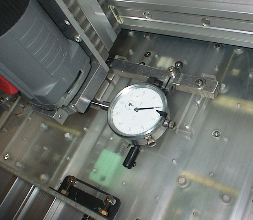
    I mounted up a dial gauge and did some tests on the backlash of each axis;

    X axis;
    Test 1 = 0.0032"
    Test 2 = 0.0032"

    Y axis;
    Test 1 = 0.0027"
    Test 2 = 0.0027"

    Z axis;
    Test 1 = 0.0006"
    Test 2 = 0.0007"
    Test 3 = 0.0007"

    The Z axis backlash is much less as I have a tighten-down screw on that leadnut making that nut significantly tighter, and of course the weight of the Z axis assembly and router.

    Now what to do with the X and Y axis backlash? I can easily compensate in software but I'm not sure if this is the right thing to do. When the router is running I measure about 0.001" of vibration on the Z axis plate, and the X and Y backlash totally disappears, which explains why it cuts perfect circles with a cutting tool. The only time backlash is evident at all is with extremely fine cuts, like when doing fine engraving.

    I might post the question in another thread and let the backlash experts have a stab at it.


    (Large picture because forum image attachments seem to be broken today... )


Page 1 of 6 1234 ... LastLast

Tags for this Thread

Posting Permissions

  • You may not post new threads
  • You may not post replies
  • You may not post attachments
  • You may not edit your posts
  •  


About CNCzone.com

    We are the largest and most active discussion forum for manufacturing industry. The site is 100% free to join and use, so join today!

Follow us on


Our Brands

DIY hobby small plastics mill/router

DIY hobby small plastics mill/router