Reply with Quote
Maybe? And maybe?Originally Posted by G59


While I highly respect your input and knowledge, I thought previous posts may have taught you! As others may have overseen things that may be quite obvious to you?
I'm a slow learner???
I think I'm less rude now LOL
Maybe? And maybe?
Why is your z currently painfully slow? It should do 5m/min with that screw? The motor could take it much faster but that screw won't allow it. You could have 3:1 reduction and still get 5m/min rpms.
Sounds like your screws are all out of alignment.
I have same screw for my z with a nema 23 on it. I cant make it back drive short of jumping up and down on it even then I doubt it would budge. This is with the motor unpowered. If you screw had zero preloading and it does drop, then applying some preloading with larger balls could be the fix.
Sorry hope I'm not sounding rude, just a little confused.

No, you got it wrong. All things equal, 24V control wiring would run at a lower current (for example, a 5V relay coil would draw more current than a 24V coil of the same size relay) and generate less noise. What's more important, it would also be more tolerant to the noise generated by other devices.
It is simply not a very good idea to run 5V logic level through a cable several meters long in a machine full of high power motors and high frequency drives.
I see It was just speculation.
What's more important, it would also be more tolerant to the noise generated by other devices.Agree 100%.It is simply not a very good idea to run 5V logic level through a cable several meters long in a machine full of high power motors and high frequency drives.
Hi Christian,
If I may give you some advise from experience:
1) I don't think that the way you wired the limit switches are not of the most ideal setup, i.e having common positive and negative supply. I would have wired them separately using shielded cable and grounded at the source of power supply. This is where and only here ALL grounding should be done. Grounding is a very tricky thing especially with electronics - Trust me I've been through this many times!! So if you have short cut grounding, I would get rid of this issue first and give it a try.
2) I would increase the voltage supply for the limit switches to 24 V but wouldn't go any higher as this should be sufficient (if I'm not sure if the max these can go to is 30V - check their data).
3) Is there anything else being fed with the same voltage supply? If so check if the power supply rating can take the load.
Sincerly these are the plausible situations I can think of, hope this would help.
Marting
Martin G
Oh! and in case you'll consider installing a pneumatic cylinder, you have ample space to fit it in on the sides, just one thing you should put a pressure regulator on it to set it's push at approx the same or slightly less than that of the Z axis weight so that the stepper could work at a lesser load.
Marting
Martin G
I'm not saying MY Z.. I'm referring to a 5mm lead ballscrew driven by a 1200in-oz stepper, attaching it to a planetary gearhead as you propose.
Also, the main reason for using a ballscrew in the first place is for its efficiency, which should be around 90% or more, about 2-3 times as efficient as a comparable trapezoidal screw and bronze nut. Which means it's backdriveable. Using oversize bearing balls is for removing axial play, not for back drive control. You end up wasting energy overcoming the torque needed just to turn the screw, where the main purpose of the ballscrew is to use the efficiency to allow a smaller motor.
I have ballscrews here up to 2mm lead C0 precision and I can easily backdrive it by hand. If you can't backdrive a 5mm screen something's aniss, or you have a relatively light Z axis.
If I remember this machine is fir shaping tooling board, not hard milling.
Wow what happened here over night? Lots of activity, lovely.
About the Z pneumatic cylinder:
I gave H&H a visit today and had a second look at their 19m long 5 axis machine, I asked him what the purpose of the two cylinders on that machine was, he said they're to take the bulk of the weight so that a smaller motor can be used. Sometimes they'll not use cylinders and just go with a bigger motor that is water cooled and a shorter screw pitch (something like 12mm instead of 20mm), because it's constantly outputting more torque to hold the extra weight. He didn't mention anything of ballscrew wear. All arguments considered, plus the fact that I know my Z axis doesn't fall even when the motor is off, I've concluded that I don't plan to install a cylinder unless I find that I actually need one.
I have tested the Z motor and found that it overshoot (I think that's the right term) itself at a about 2000RPM with no load, as opposed to the NEMA23s topping out at about 4500RPM. That may not be great for super high speed Z motions, but I would speculate that the increased torque will help more than increased RPM over what I already have. An important factor in high speed machining is having the ability to accelerate fast, and that extra torque will help with that, because I doubt I'll ever be machining at a feedrate faster than the Z motor can handle.the stepper motor chosen for the Z is complete overkill, and likely will lead to poor higher speed performance, which is needed for 3D contouring of engineering composites. Not to mention "cogging" issues which may telegraph onto the surface.
Understand though, that I'm far from an expert on the topic, just someone who has cogitated on it for a day.
12V vs 24V vs 48V:
You make a good point CitizenOfDreams. I don't have 24V already in my controller, I do still have 12V, so I might test a 12V relay some day and came back with the results.
louieatienza:
Thank you, kind person. Your scissor idea seems like a pretty nice idea, but a bit complicated to implement in my mind. And I do agree that 16mm is too small a diameter for a screw that long, but being where I am and the budget I was on at the time, my only options were this for about $200 or $800 for a 40mm one with double ballnuts.You machine is looking great! An idea for the ball screw support: You can make another one for the other side, then make or repurpose some scissor mechanisms, this way each ball screw support will be automatically centered. Though I feel 16mm may be a tad small for your axis length. Another way, possibly, would be to machine the non-driven end to accept a fixed-end bearing block, and use Belleville washers to keep the screw under tension while still allowing for thermal expansion.
And I'm not sure how effective putting tension on the other end of the ballscrew would be, it's very small vibrations that start it, then they grow bigger until is jams the system. I mean, it may help, I'm not sure. I am sure of one thing though, I don't have a lathe to machine the end of the ballscrew and I'm not prepared to pay for that right now. During my visit to H&H today, he asked me how much I was expecting the rotary head to cost in machine time. I said "I'd like to keep it under $2000". He shook is head slightly and said "I wouldn't even consider it". Which tells me it's going to be many thousands. So for now I'm searching for ways to make as much of it myself on my Sieg X2 mill. *adds boring head to shopping cart*
marting:
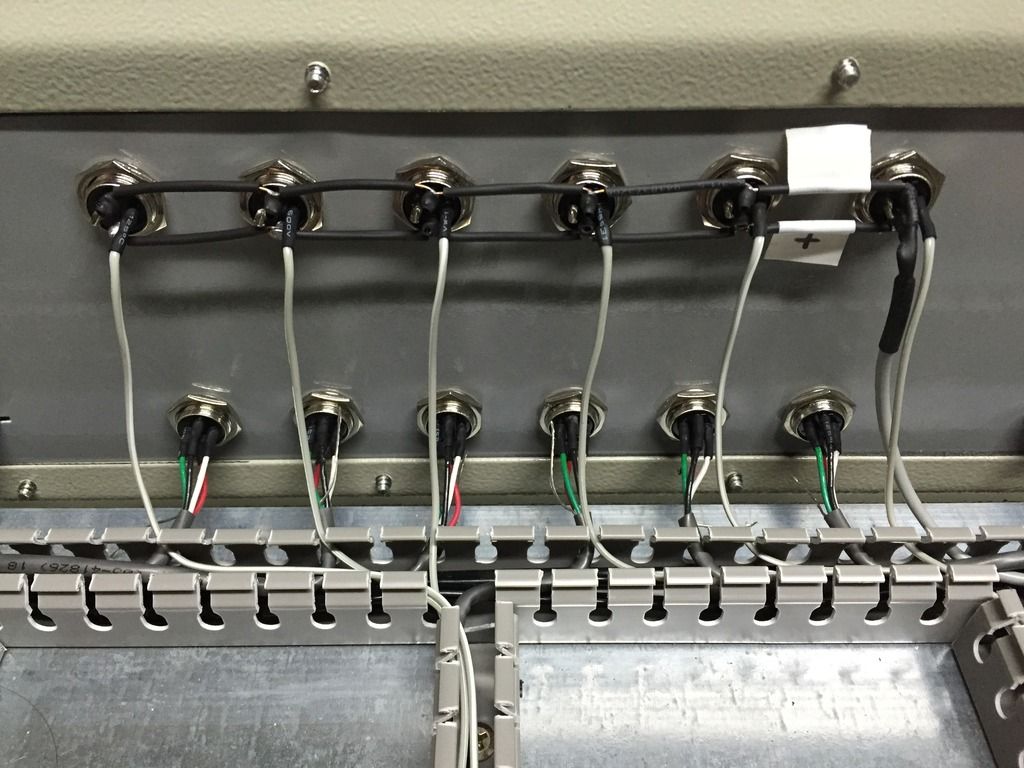
1) Are you referring to those black wires connecting all the limit switch positive and negative pins in this picture?If I may give you some advise from experience:
1) I don't think that the way you wired the limit switches are not of the most ideal setup, i.e having common positive and negative supply. I would have wired them separately using shielded cable and grounded at the source of power supply. This is where and only here ALL grounding should be done. Grounding is a very tricky thing especially with electronics - Trust me I've been through this many times!! So if you have short cut grounding, I would get rid of this issue first and give it a try.
2) I would increase the voltage supply for the limit switches to 24 V but wouldn't go any higher as this should be sufficient (if I'm not sure if the max these can go to is 30V - check their data).
3) Is there anything else being fed with the same voltage supply? If so check if the power supply rating can take the load.
Sincerly these are the plausible situations I can think of, hope this would help.
Marting
If that is what you're referring to, then I can't see how it would make a difference to have a wire for each pin. They all connect to the same positive terminal on the power supply anyway, this just cuts it all down to one wire to transport the power there. The vast majority of the wires in the machine are shielded, granted about half of them aren't grounded/earthed right now.
And on the topic of grounding, due to differences in international standards in what term means what, I'm a little confused. When you say 'grounding' do you mean connect the shielding of the wires to the ground that has a stake in the ground or 'ground' as in connect the shielding to the negative side of the power supply?
Another thing, also while visiting H&H today, I asked him how they handle EMI, he was a little hazy on the topic, I don't think that's really his area of expertise. But he did say that one of his clients or someone who was working on a similarly size machine to his was having trouble with their spindle, he spent days working on it. Then the manufacturer of the spindle told him to make sure the ground wire was grounded at both ends, that fixed the problem. So your statement "This is where and only here ALL grounding should be done" might not be a sound as you think.
2) As I stated above, I'll try 12V first now, because I already have 12V in the controller. The new mechanical switches can take 240VAC (don't know about DC), so I should have plenty of room for increasing voltage anyway.
3)When I was using the 12V supply on the proximity switches the 12V supply was feeding nothing but the switches, well within its 2A limit. Now that I'm on mechanical switches, I've been using 5V, which is also supplying the breakout board
your nema 34 will exceed that screws maximum rpm which is around 1.5k so without going up in screw pitch I'm afraid your maxed out anyway. And acceleration wise the 34 having more torque is the better option of the two like you say.
ChristianLL
On your limit switch issue seems like something is clearly wrong. You can mechanically play with the wire and get it to be seen by Mach4. EMI comments are very common on limit and home switches once you have the spindle running but in your case that should not currently be an issue. I recommend shielded cable for all limit and home switches. I also suggest you run them at 12V or 24V as this will save you a huge number of headaches once you start up your spindle. The EMI generated from a spindle causes many electrical issues you you have not taken the appropriate precautions. To avoid issues with noise of long limit switch wires, you can run them at 12/24V and have that power connect to a 12/24V relay near your controller. The contacts on the relay will have one side of the NC contact tied to the port input pin, and the COM side tied to ground. In the normal state when you are away from the limits switch contacts are closed so current will flow and activate the relay, so the NC contact will not be seen by MACH4. When the limit switch is tripped this will kill the current to the relay and the NC contact will now provide a ground to the input pin of the controller. Since the 12/24V is isolated from the controller by the relay this presents no issue to the controller and since the wires to the controller from the relay are very short they will not pick up EMI noise. I have this implemented on my machines and the spindle never causes an issue now. You need to stay on the input/output screen in MACH4 to troubleshoot this issue. Good Luck, you have a wonderfully looking build and obvious are a talented person.
Russ
marting:
1) Are you referring to those black wires connecting all the limit switch positive and negative pins in this picture?
If that is what you're referring to, then I can't see how it would make a difference to have a wire for each pin. They all connect to the same positive terminal on the power supply anyway, this just cuts it all down to one wire to transport the power there. The vast majority of the wires in the machine are shielded, granted about half of them aren't grounded/earthed right now.
And on the topic of grounding, due to differences in international standards in what term means what, I'm a little confused. When you say 'grounding' do you mean connect the shielding of the wires to the ground that has a stake in the ground or 'ground' as in connect the shielding to the negative side of the power supply?
Another thing, also while visiting H&H today, I asked him how they handle EMI, he was a little hazy on the topic, I don't think that's really his area of expertise. But he did say that one of his clients or someone who was working on a similarly size machine to his was having trouble with their spindle, he spent days working on it. Then the manufacturer of the spindle told him to make sure the ground wire was grounded at both ends, that fixed the problem. So your statement "This is where and only here ALL grounding should be done" might not be a sound as you think.
2) As I stated above, I'll try 12V first now, because I already have 12V in the controller. The new mechanical switches can take 240VAC (don't know about DC), so I should have plenty of room for increasing voltage anyway.
3)When I was using the 12V supply on the proximity switches the 12V supply was feeding nothing but the switches, well within its 2A limit. Now that I'm on mechanical switches, I've been using 5V, which is also supplying the breakout board[/QUOTE]
Limit switches:- Theoretically having a common supply makes perfect sense, but in practice the supply conductors are still exposed to EMP (Electro Magnetic Pulse) emitted from anything that generates a spark like the router and relays or EMI (Electro Magnetic Induction) generated by nearby AC carrying conductors, transformers etc. So here is where the shielding comes in, grounding is like when you connect the wire to the outer metal body of a machine (not like when connecting to 0V, as in the electronics terms). Having grounding at supply source only ensures that A) any induced voltage is carried right out of the system immedietly and B) ensuring that there is a constant earthed value through out the whole system. Many times having bridged grounding (i.e. connected in series) tends to leave a minute voltage build up which is enough to start messing around with your mind wondering what the hell is going on. Current supply of 2A for the limit swithches should be just about ok if the max current supply / drain of each is 300mA.
I had a similar problem, when my vacuum pump goes on, the E stop is triggered and managed to solve to problem by locating it farther away from the CNC controller. Naturally this isn't your case but the point is to indicate hoe sensitive electronics are to these things.
I hope this gives you a better understanding.
Martin G
I don't think it's complicated. You can just find one and repurpose it. If you mount the bal screw support to the center of the scissor mechanism, it should center the support reasonably on center of the unsupported part of the screw. And since the screw is longer than the axis travel you should not lose any travel.
Also for ball screws, having both ends fixed gives the screw higher column stiffness, and therefore longer length given same diameter as fixed/free end fixity. And thus higher critical speed.
It may seem like a simple solution, but in general daisy chain wiring should be avoided as much as possible. A star connection to the power source is best. You wouldn't connect the power to the stepper drives that way, at least you shouldn't.If that is what you're referring to, then I can't see how it would make a difference to have a wire for each pin. They all connect to the same positive terminal on the power supply anyway, this just cuts it all down to one wire to transport the power there.
I had some issues due to interference, where some cheap ferrite chokes seemed to solve the problem.
Well without looking at the torque curve charts for your stepper versus power supply voltage, it's pretty simple to consider the max federate you need for cutting and rapiding, multiply that by the pitch of the screw, and you should know the rpm needed from the stepper to do the job. A look at the torque curves of both steppers will give you an idea of the torque produced by each stepper at those speeds, which is way more important than the stall torque rating of the stepper, which is at full step at very low speed. Does higher stall torque mean better acceleration? Not necessarily, since the larger motor may have a larger detent torque and inertia to overcome, before it sees any frictional or mass load. This can cause vibration also.I have tested the Z motor and found that it overshoot (I think that's the right term) itself at a about 2000RPM with no load, as opposed to the NEMA23s topping out at about 4500RPM. That may not be great for super high speed Z motions, but I would speculate that the increased torque will help more than increased RPM over what I already have. An important factor in high speed machining is having the ability to accelerate fast, and that extra torque will help with that, because I doubt I'll ever be machining at a feedrate faster than the Z motor can handle.
Understand though, that I'm far from an expert on the topic, just someone who has cogitated on it for a day.
Last edited by louieatienza; 06-15-2016 at 09:40 PM.
Mach3 can figure out which limit switch has been triggered when switches are wired in series. It does so by keeping tabs on the (total) position of the axis and which axis was in motion at the time of the trigger.
.
So this frees up 4 inputs on your breakout board. LinuxCNC has same capability.
In series you have 1 wire doing all the limit switches. You can do the same for all home switches. So limit and home now take up only 2 inputs.
Wires that run in parrallel like the way you wired your connectors, are more suseptible to electrical noise especially if in proximity of or near generated PWM signals or High Frequency PWM drives and there outputs.
Check in your cabinet for possible noise generating culprits. For example, the two conductors carrying the power to your drives(even though it's DC) should be run in a twisted pair. This practically eliminate the possibility of noise radiating from them and also makes them immune to noise. Check that all AC lines are away from signal wires.
Although your parrallel connections look cleaner and simpler, it will always be suspect when false triggers become common place and eventually cripple your progress. This is a simple fix. Desolder your switches and run them in series.
That's exactly what I plant to do in my quest to fix the limit switches. But as previously mentioned, a lot of money is about to be spent on the rotary head, so limit switches are a second thought for now. Thanks for your suggestion man.On your limit switch issue seems like something is clearly wrong. You can mechanically play with the wire and get it to be seen by Mach4. EMI comments are very common on limit and home switches once you have the spindle running but in your case that should not currently be an issue. I recommend shielded cable for all limit and home switches. I also suggest you run them at 12V or 24V as this will save you a huge number of headaches once you start up your spindle. The EMI generated from a spindle causes many electrical issues you you have not taken the appropriate precautions. To avoid issues with noise of long limit switch wires, you can run them at 12/24V and have that power connect to a 12/24V relay near your controller. The contacts on the relay will have one side of the NC contact tied to the port input pin, and the COM side tied to ground. In the normal state when you are away from the limits switch contacts are closed so current will flow and activate the relay, so the NC contact will not be seen by MACH4. When the limit switch is tripped this will kill the current to the relay and the NC contact will now provide a ground to the input pin of the controller. Since the 12/24V is isolated from the controller by the relay this presents no issue to the controller and since the wires to the controller from the relay are very short they will not pick up EMI noise. I have this implemented on my machines and the spindle never causes an issue now. You need to stay on the input/output screen in MACH4 to troubleshoot this issue. Good Luck, you have a wonderfully looking build and obvious are a talented person.
Thanks for the clarification. It really does boggle the mind thinking how sensitive electronics can be, why have I never heard of personal computers having these problems? I've got the computer leaning up against the 72V 20A toroidal power supply and it has no problems, yes my simple limit switches are all over the place! Crazy.Limit switches:- Theoretically having a common supply makes perfect sense, but in practice the supply conductors are still exposed to EMP (Electro Magnetic Pulse) emitted from anything that generates a spark like the router and relays or EMI (Electro Magnetic Induction) generated by nearby AC carrying conductors, transformers etc. So here is where the shielding comes in, grounding is like when you connect the wire to the outer metal body of a machine (not like when connecting to 0V, as in the electronics terms). Having grounding at supply source only ensures that A) any induced voltage is carried right out of the system immedietly and B) ensuring that there is a constant earthed value through out the whole system. Many times having bridged grounding (i.e. connected in series) tends to leave a minute voltage build up which is enough to start messing around with your mind wondering what the hell is going on. Current supply of 2A for the limit swithches should be just about ok if the max current supply / drain of each is 300mA.
I had a similar problem, when my vacuum pump goes on, the E stop is triggered and managed to solve to problem by locating it farther away from the CNC controller. Naturally this isn't your case but the point is to indicate hoe sensitive electronics are to these things.
I hope this gives you a better understanding.
Not sure I know what you mean here. Also, the ballscrew on the X (the one that's having problems) is actually about the same length. The thread is exactly the same length, the mandrels are what make it a little longer.I don't think it's complicated. You can just find one and repurpose it. If you mount the bal screw support to the center of the scissor mechanism, it should center the support reasonably on center of the unsupported part of the screw. And since the screw is longer than the axis travel you should not lose any travel.
You make a good point, my drivers aren't wired in parallel, they all have separate leads. Looks like the limits are getting there own supply wires. Aren't they lucky huh? Spoilt little devils.It may seem like a simple solution, but in general daisy chain wiring should be avoided as much as possible. A star connection to the power source is best. You wouldn't connect the power to the stepper drives that way, at least you shouldn't.
I knew Mach could distinguish the inputs for homing, I wasn't aware Mach3 could figure out which limit it was likely hitting, although it wouldn't be hard to program that logic - just compare which soft limit it's closer to and you know which limit it's likely hitting. I'm not sure if Mach4 does this, and I'd personally like the idea of separate switches, it might also help keep the signal for each switch cleaner of noise seeing as it's not one MASSIVELY long wire running around the entire machine to get to each switch.Mach3 can figure out which limit switch has been triggered when switches are wired in series. It does so by keeping tabs on the (total) position of the axis and which axis was in motion at the time of the trigger.
.
So this frees up 4 inputs on your breakout board. LinuxCNC has same capability.
In series you have 1 wire doing all the limit switches. You can do the same for all home switches. So limit and home now take up only 2 inputs.
Wires that run in parrallel like the way you wired your connectors, are more suseptible to electrical noise especially if in proximity of or near generated PWM signals or High Frequency PWM drives and there outputs.
Check in your cabinet for possible noise generating culprits. For example, the two conductors carrying the power to your drives(even though it's DC) should be run in a twisted pair. This practically eliminate the possibility of noise radiating from them and also makes them immune to noise. Check that all AC lines are away from signal wires.
I'd bet the 15A 240V AC power cable isn't helping, I might try relocating it, right now it runs from one side of the box and back (to get to the big switch).
In other news I got a quote for machining all the parts for the rotary head... $6000. So I spent a day removing all the expensive features like 90mm bored holes and left them to just basically square up the stock and spot drill holes so I could come in and finish the holes. I want them spot drilled because my mill can't fit the parts, so having the holes located means I can easily finish the job. So after submitting the new simplified drawings, head quoted $2400 + 10% tax. I told him to go ahead with that. Until an hour later I realised I could just buy all the equipment needed to make the parts for the same price. So now I'm excited to announce tomorrow morning (assuming they have everything in stock) I'm picking up an Optimum MH-28v, a 152mm rotary table with lathe chuck and some other goodies to get the job done. I also ordered a boring head and a Tormach quick tool change collet and some tool holders to upgrade my tool change times! Now I have to tell the man to cancel the entire job, I hope he doesn't get too pissed of, I'd like to maintain good terms.
Also, I've discovered a way to share the rotary head assembly file. You can view it here:
Unsupported Browser ~ A360
You can also download it if you want. I don't much care about copyright or whatever. If you make one like mine, I'd LOVE to see it.
That's all for now, I'll post some photographs of the new toys when I get them!
Sorry I'm late guys, I've been quite busy (actually busy, not just an excuse for being lazy).
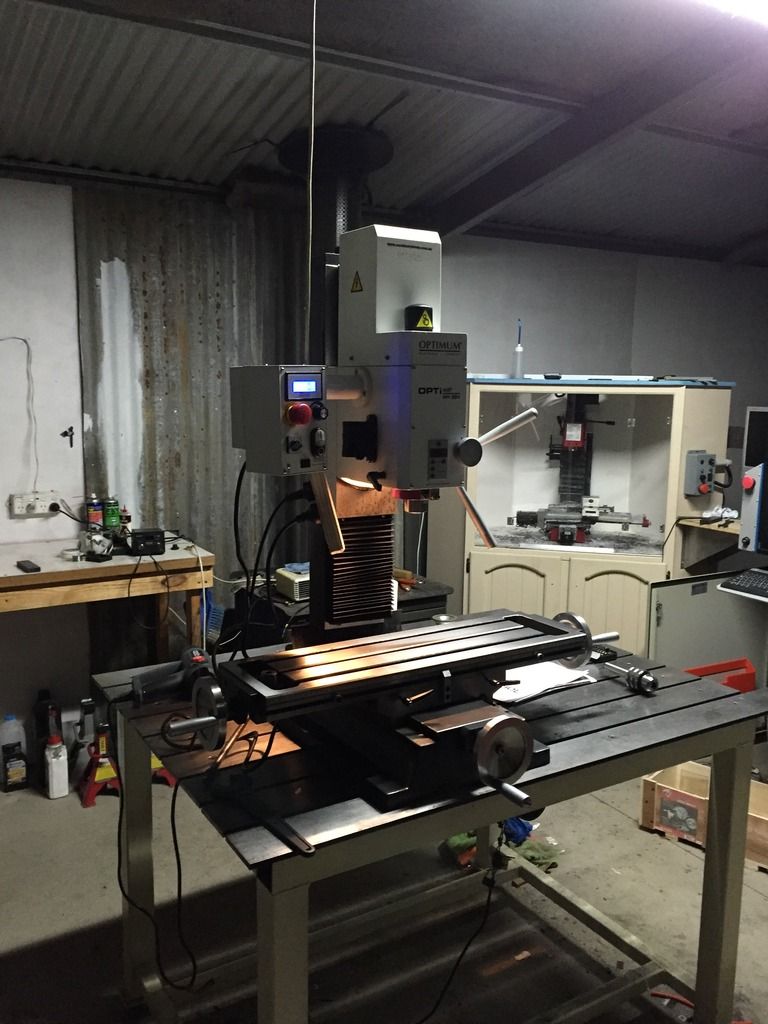
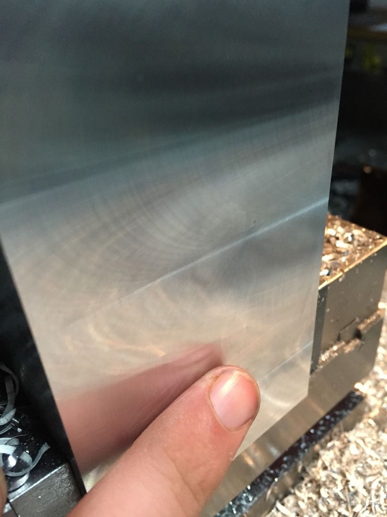
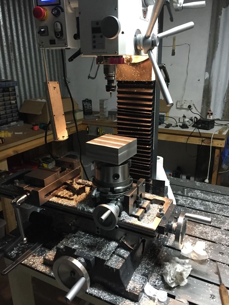
So I've got all the new equipment, I had to get a friend to make a new drawbar for the new mill to suit the Tormach TTS collet and then for the past week I've been chipping away at these chunks of aluminium (literally, HAH!). The MH-28v is a pretty nice machine as far as Chinese machines go, but the head is tilted very slightly towards me, so when I'm fly cutting, it's not cutting perfectly level, but as long as I do my finish passes in the right direction they turn out okay (still means there's a very slight peak and valley happening along the surface, but not enough to matter to me.
Anyway, pictures!
Here's the machine:
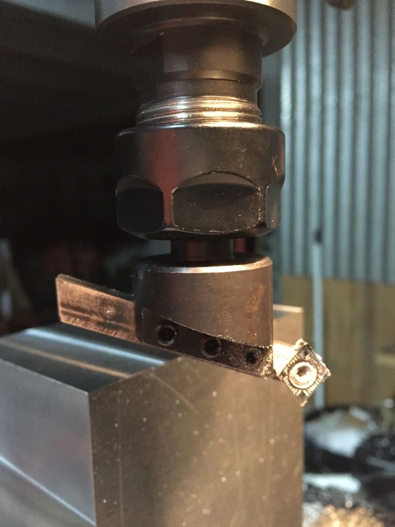
Home made insert holder bar for the fly cutter.
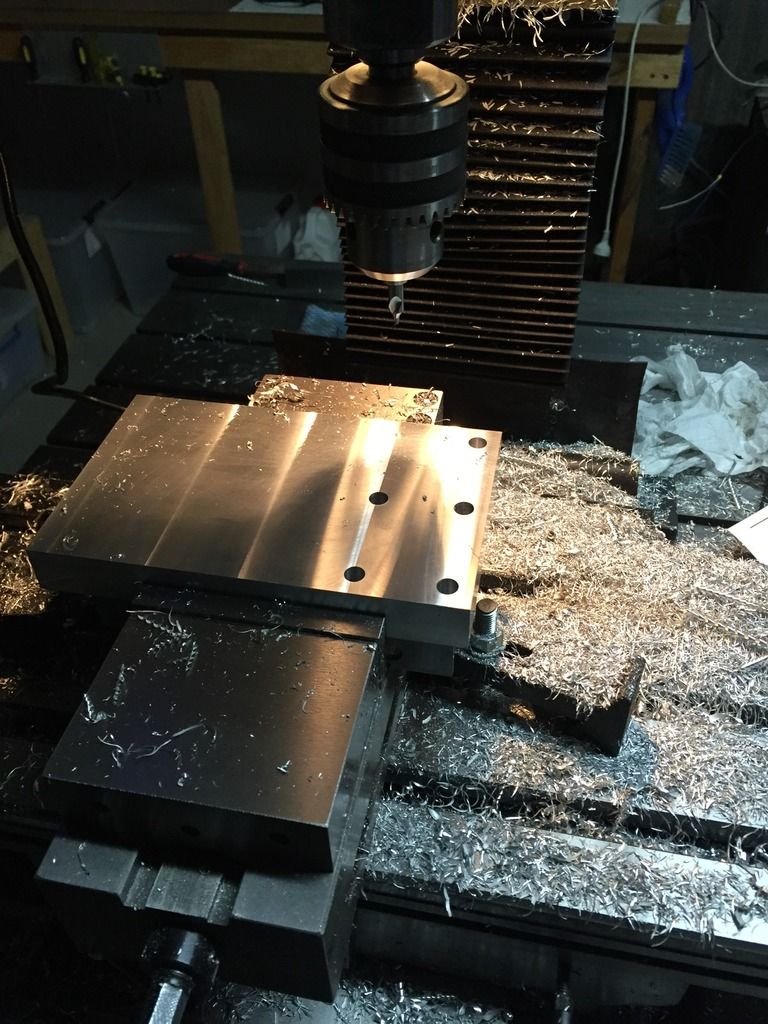
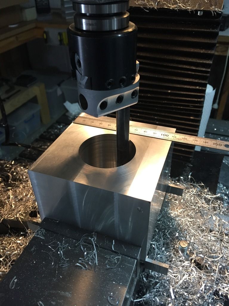
Drilling holes
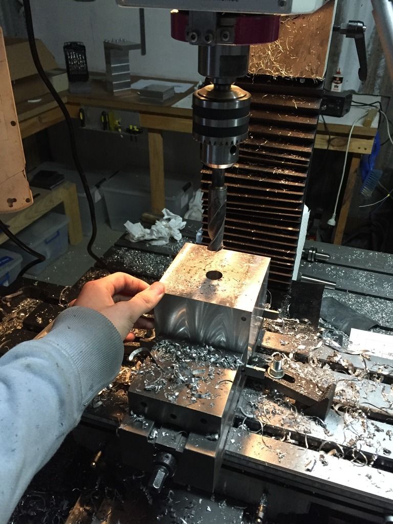
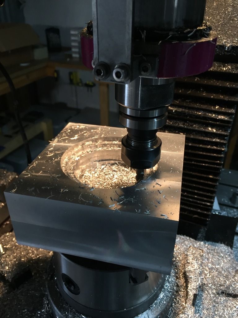
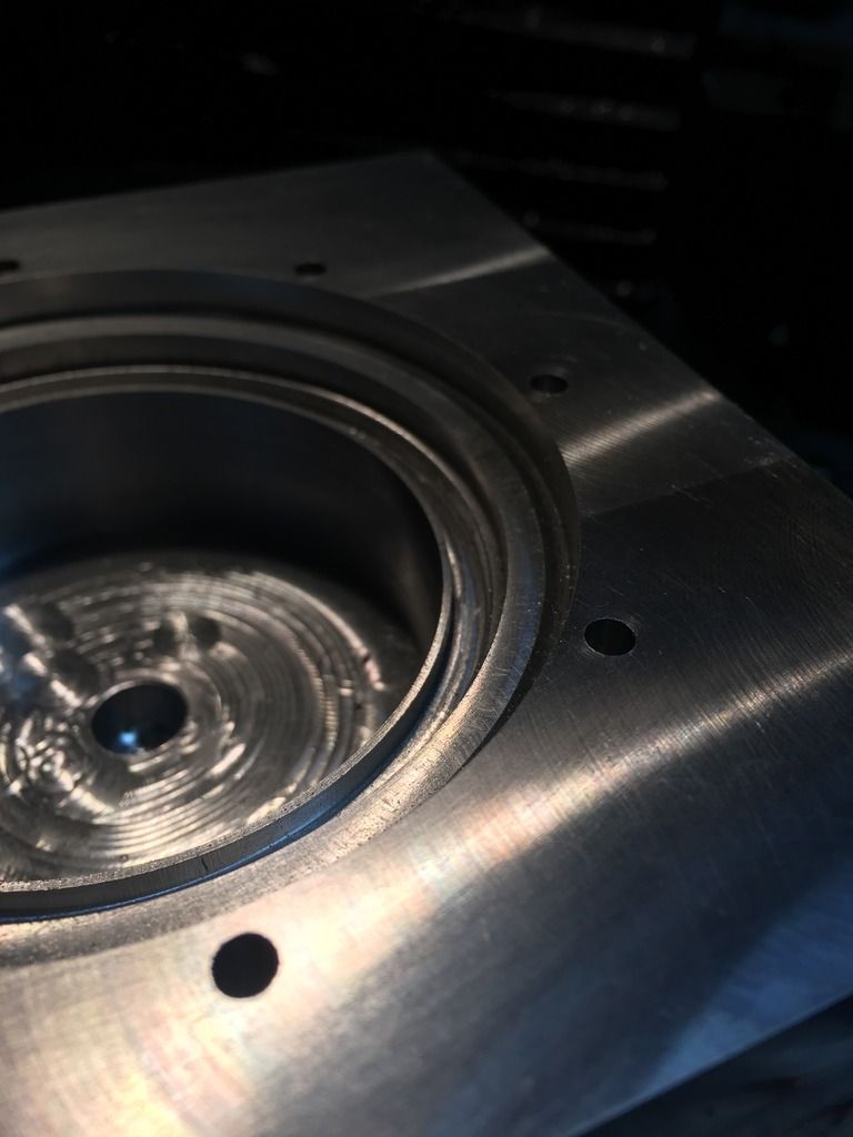
Drilling big holes! As soon as I post this, I will continue boring this hole out to 80mm... One pass at a time...
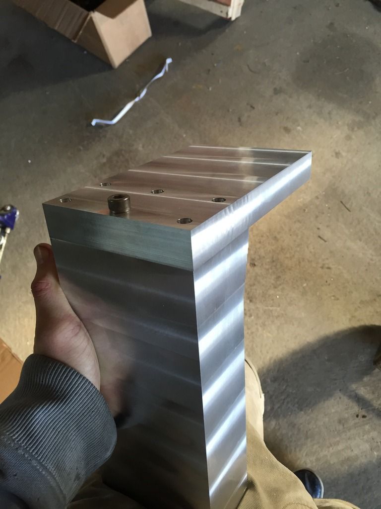
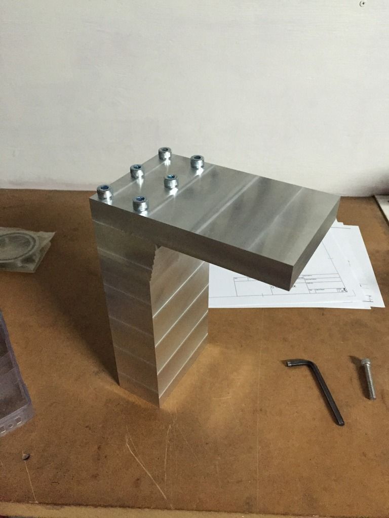
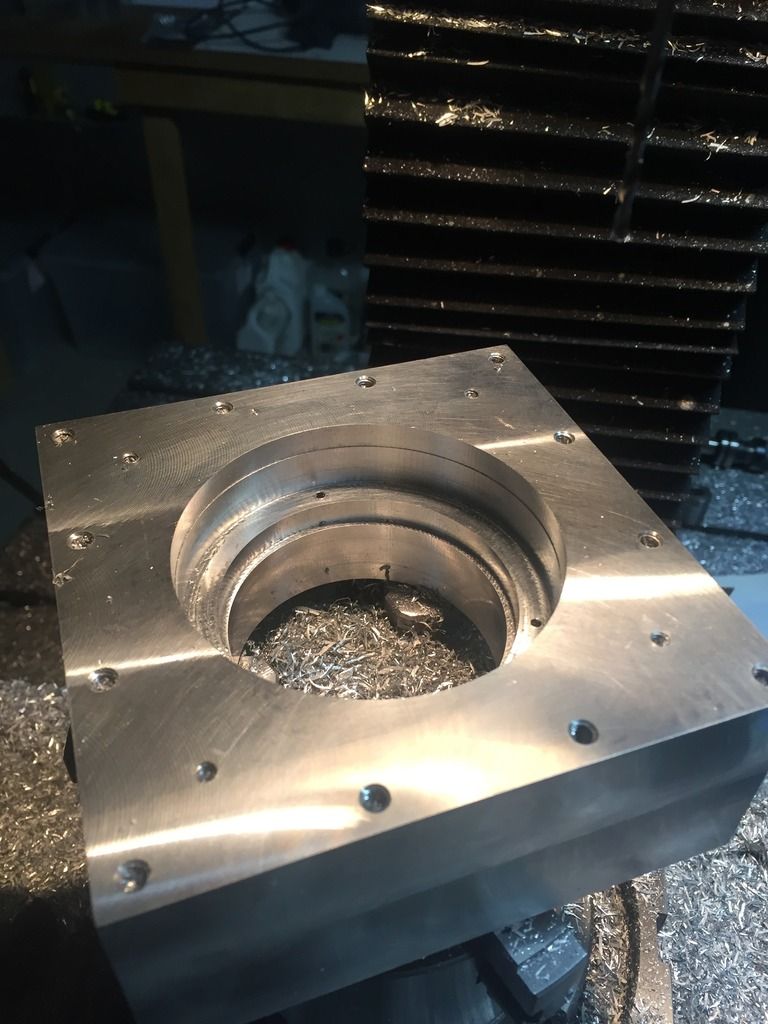
Test fitting
And that's about it for now. I'll keep you guys posted on the progress.
I would say, it's not that trivial - because hitting a limit switch usually happens when something goes on outside Mach3's knowledge and control. For instance, let's say that the X axis missed a few steps somewhere in the middle of the part. Then the spindle moved diagonally towards the machine zero, and the X axis hit the limit switch because of those missed steps. There would be no way to guess which axis hit the limit in this situation.
On the other hand, does it really matter which axis did it? Mach3's response would be the same: stop the machine, pop up the error message and let the operator sort out the mess.
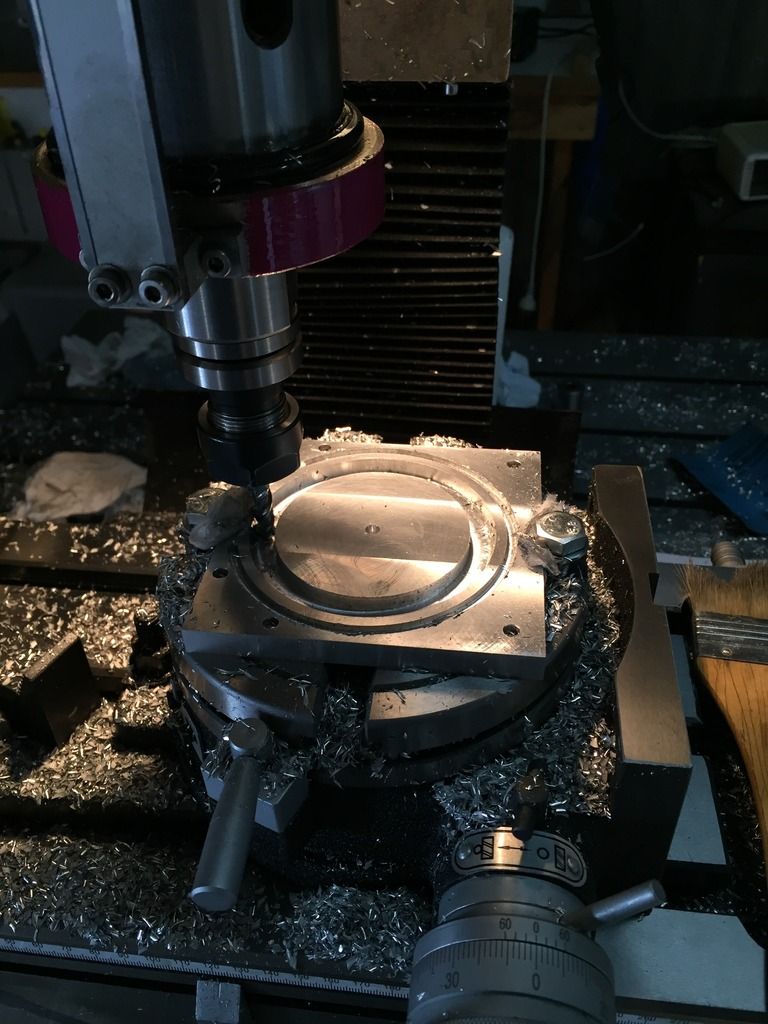
Here's that bored hole that started at 18mm and bored all the way to 80mm. It isn't at the final dimension in this photo.
Then moved on to finishing the B axis motor plate
Then set up the chuck on the rotary table. To hold the block with the jaws, I first had to cut a circular pocket with my CNC mill.
Start cutting the hole for the fancy workings
Everything's going nicely, the part looks nice...
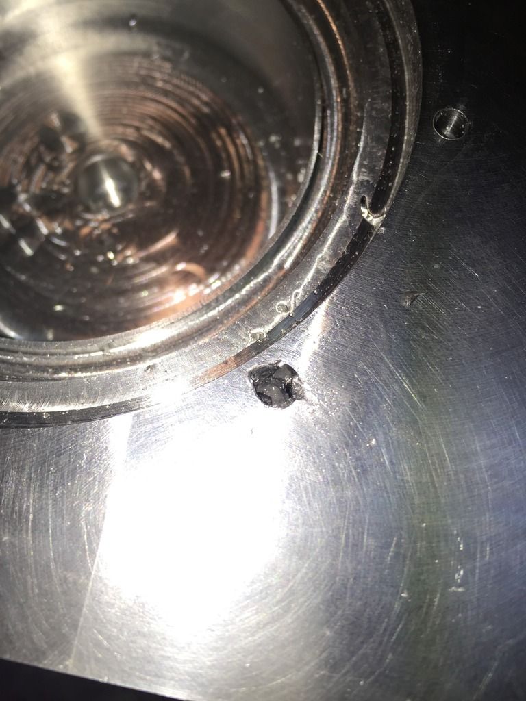
...Until I break an M5 tap 20mm deep in aluminium.Time to get out the masonry drill bit and spend an hour churning that tap to fine dust.
Somewhat disappointing that this hole took two nine hour days to cut - I really need a lathe.
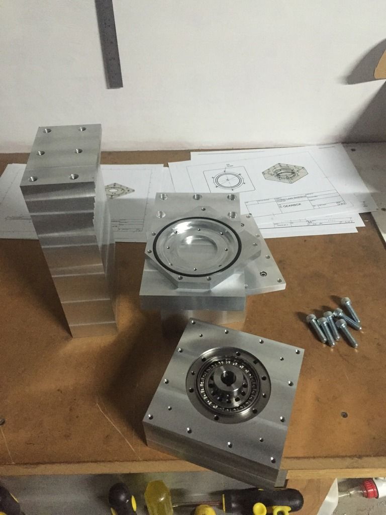
M-M-M-MONEY SHOT!!!
That's it for photos.
I just realised today that I could have bought a doughty drive for $500 less than making this one has cost me. If I already had a big enough milling machine it would have been much cheaper for me to make it, but because I did have to buy the new milling machine to make this, I've come out worse. However, I like the look of mine more, I get the pride in having built my own, and I can always sell the (practically) brand new milling machine for about $1800. Which will put me back in front.
Anyways, goodbye for now and stay happy in your hearts.
Last edited by ChristianLL; 07-05-2016 at 05:54 AM. Reason: Typos
be careful what size motor you get for your Z axis to big is bad a nema 24 around 500in oz 6 amp will be good
a 5mm lead ballscrew driven by a 1200in-oz stepper can be far to big it has a **** top speed and that's on a $000 ballscrew nut and bearings.
I got told by someone who no his stuff a stepper is better on a 10 mm pitch and a servo is better on a 5 mm pitch
nice build
<img src="https://ivxo1q-dm2305.files.1drv.com/y4mENMmTr_Cabc7pR0FUdB6gtbADq2JbuG4_rGy0eBQvLJx19pTi6TqMUIJN0xgOyDIc0gWoxYhS38HpbSTFGdfaK-o42IOU6jczrhDpfpCOTNGL1X6hvZCbgj0y35gqmq1YGTrWwShYGV-C7lXA2esy0Pi_WfnBSyroDLSGXwce4uSr1U7op7srdi78rispHCa_K4aFlTlJPVkkNWMfgh_Tg?width=60&height=60&cropmode=none" width="60" height="60" />
Being Disabled is OK CNC is For fuN