


 Reply with Quote
Heh...maybe time for me to upgrade yet again? I was waiting for something like that.


I'm working with Michael at CNCFusion on a new ballscrew upgrade for the X3 Mills. Well, working is giving me way too much credit... I found the angular contact bearings that are being used, but other than that I just bought the prototype and will be installing it on my X3 to get any bugs worked out before Michael makes these available.
I'll let the pics do the talking, needless to say, I'm now very glad that Syil couldn't supply me with a hardware only CNC upgrade kit when I asked. The new ballscrews Michael found are works of art. As nice or nicer than the ballscrrews on some the the semiconductor fabrication robots I've worked on. I'm not saying it's as nice as some of the $50,000 ballscrews I've seen, but very nice all the same.
Hope I don't say this too much, but I'm very, very happy with this conversion kit. I'm very glad I didn't build my own conversion using standard Nook ballscrews.
Because this is the prototype from Michael at CNCFusion, I can't answer any questions about pricing, and some details might change as I get things fitted up and make sure no mods are needed. But I'll answer any question I can.
I really like my new toy.
-Matt
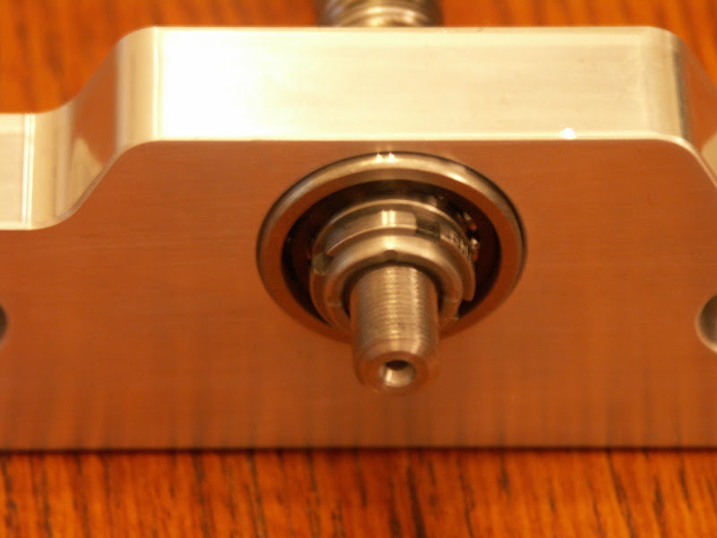
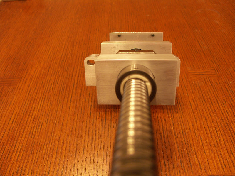
X axis thrust bearing block showing preload nut:
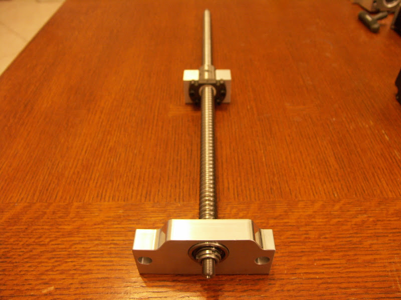
X axis ballscrew:
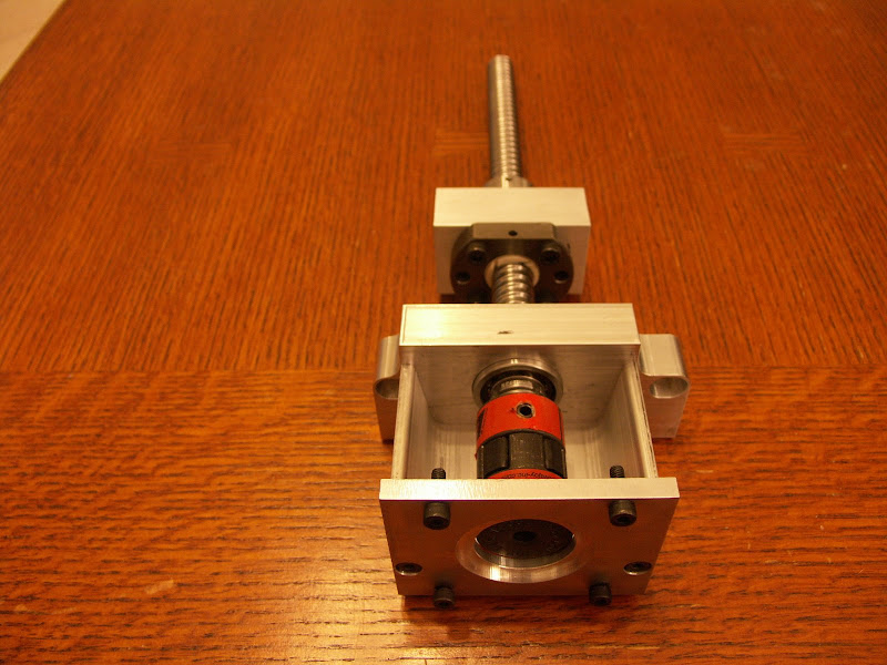
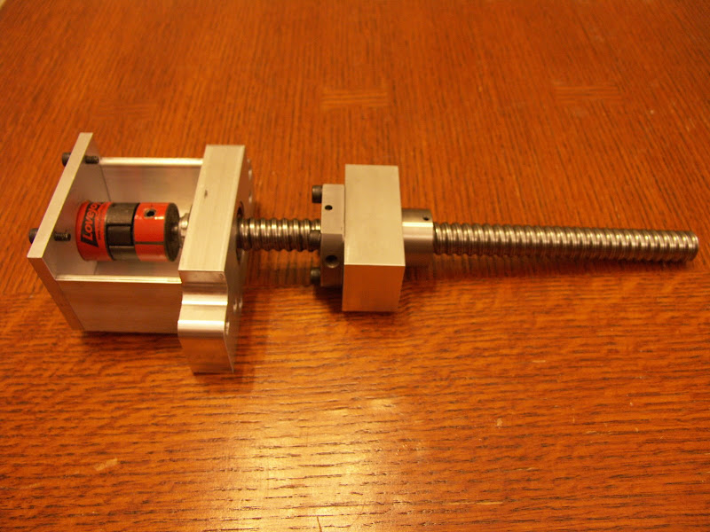
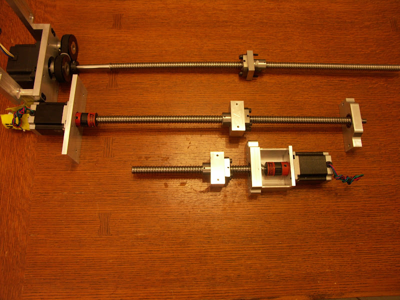
Y axis screw showing motor mount and lovejoy coupling:
Y axis again:
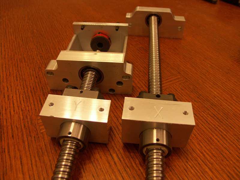
X axis ballnut showing integrated wiper:
X and Y ballnuts:
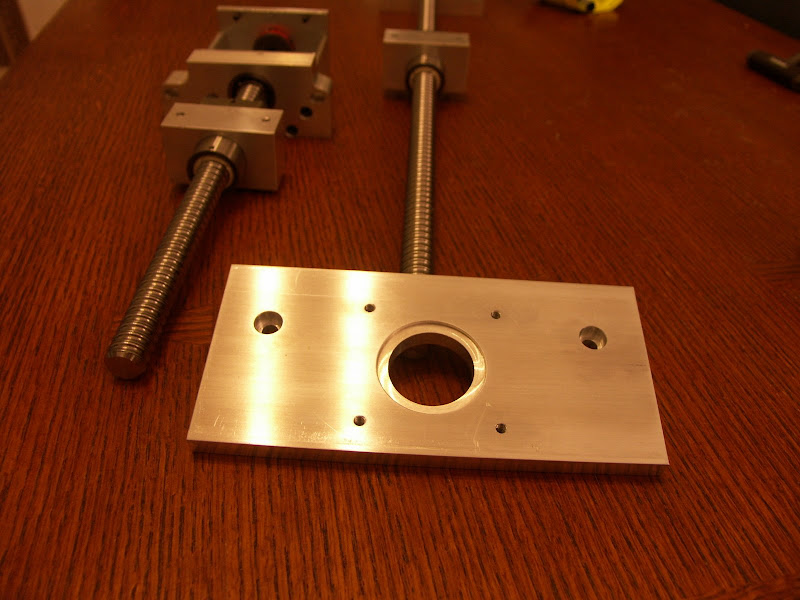
X motor mount:
All three side by side:
Similar Threads:
Last edited by cobraphx; 03-11-2007 at 12:57 AM. Reason: Update pictures
Heh...maybe time for me to upgrade yet again? I was waiting for something like that.
Pretty nice looking!
A) What's up with the ballnuts? Are the ballnut options still the same, meaning plain, double, or preloaded single? Which do you have and what backlash are you seeing?
B) How do you change the thrust bearing pre-load? It looks like there is a splined nut... That's good... what's the other part that you hold to apply torque? Do I need !@#$%@#$% strap wrench to get a grip on the ballscrew itself?
Thanks!
-Jeff
The ballnuts and ballscrews are part of a new upgrade option that will be offered by Michael at CNCFusion.com . My understanding is that Michael found a new supplier for these. They are very nice.
As for backlash, I literally just took them out of the shipping box on Friday night. It will be a while before I can get everything installed and post backlash measurements.
I received the kit just as you see it. Michael will have to answer the backlash setting procedure. Not sure how he immobilized the screws while tightening the retaining nuts.
-Matt
Wow, that is probably the best looking kit I have seen for an X3. This is certainly catering to the high end. I am interested in knowing what is done about preloading the angular contacts. Uniform spacers for each set, and instructions on how much torque to apply to the bolts which clamp the outer races together?
I sure wish that motor mounts / bearing blocks would be availlable for a timing pulley arrangement. I want to run servos on either an X3 or a Lathemaster mill.
Why can't you use a servo connected straight? Is it a torque/power vs speed curve issue?
-Jeff
Is there any loss of travel with the kit?
Deviant,
My tape measure says there isn't any loss of travel. But I can't be 100% sure what the travel will be until I get everything installed. I should be able to get some numbers before the end of the week.
-Matt
depending on the costs, perhaps I'll order this kit instead of fabricating my own... time will tell.
Any updates on this?
We had to make a change to the Y axis mounting block in order to center the six and a half inches of Y axis travel under the spindle. I'll be taking new pics and making an update when I get the revised part from CNC Fusion. Hopefully it won't be much longer.
-Matt
Hey guys! How is the new Y-axis design coming along... any updates on the progress of this new kit?
It's looking really nice so far btw... can't wait to hear the results on this one.
Last I heard, they have fixed the y axis issue and they are waiting on their order of ball screws.
I'll post pictures of my pre-ordered kit when the slow boat from china arrives.
The Y axis revisions turned out very nice. The X axis travel is now 16.25" and the Y axis travel is now covers the entire table and is 6.75". Sorry I don't have any backlash numbers yet... I'm trying to get my electrical setup sorted. Haven't decided how to wire up the optical switches I bought for home / limit. Or if I should even bother with limit switches.
-Matt
I was under the impression that those Lovejoy couplings were not completely zero backlash ? or am I mistaken ?
PR.
www.mcmaster.com
search for oldham.
They list it as zero-backlash (no play)
Depending which one you get.
I'm far from an expert, but I'd say the lovejoys would stay zero or very close to zero until you put enough force on them to compress the isolator. I don't know the hardness of the isolator portion, so I won't even hazard a guess how much force is required to compress it. But I'd guess that it's significant... probably more than my steppers can generate.
-Matt
That's what I was taught, Oldham's with the zero torque driving plate were, with the other type were not and the same for lovejoy couplings.Originally Posted by Deviant

Another thing, although it doesn't apply to this post, why when doing CNC conversions do most people mount their stepper out in fresh air on 4 pillars looking like a grandfather clock ?
The number of conversions I have seen looking like this is beyond count.
Is it too much to ask for a bit of engineering instead of clockmaking ?
PR.
I think that's so they get hotAnd as an attempt to be on topic... Sexy ballscrews you have there Cobra
Keith
 Posting Permissions
