Reply with Quote
I just took some nuts and used a bench grinder to grind a wedge. Mine just holds a aluminum angle to protect the limit switches.
OOPS, I think I used bolts in the slots and nuts outside.
Don


I am going to wait till tomorrow and give Grizzly a call. If the news is bad then I will make some. It sucks getting parts out of those guys.
I just took some nuts and used a bench grinder to grind a wedge. Mine just holds a aluminum angle to protect the limit switches.
OOPS, I think I used bolts in the slots and nuts outside.
Don
Last edited by DonKes; 12-29-2013 at 11:14 PM. Reason: OOPS
Graham, you are really building a nice machine. That oiler plumbing is awesome; love the anodized parts too. Keep up the great work, can't wait to see it cutting. --md
That is not a bad idea, thanks!Originally Posted by DonKes

Thanks for the encouragement mduckettI got the idea for the oil lines from a lathe conversion and from an RF45 conversion (can't remember whose)
I have been following your build as well. I have been taking notes on your flood coolant systemDon't be surprised if you see me doing something similar
I have been putting a lot of time into the mill these past few days so here is an update:
I revisited my spindle. Initially I had over tightened the bearings when I assembled it and it was running extremely hot. I thought I had ruined the bearings, but luckily I didn’t. I took the spindle back apart, cleaned out the old grease and reassembled it. Before I did I sanded the mounts for the bearings a little bit so the fit was a little better. This time when I tightened everything up I did not crank on it. I ran it for 30 min at 1250 rpm and it was only warm to the touch.
While I was working on the spindle, I looked at switching to angular contact bearings, but I decided against it for the following reasons:
I would have half of the dynamic load rating I get with my current roller bearings.
I already switched to SKF bearings (got them through MSC) which I can safely run up to 8000 rpm.
Here are the links to the bearings I got:
Tapered roller bearings, single row - SKF.com/Products
Tapered roller bearings, single row - SKF.com/Products
It seems like the real limit to spindle RPM is the large bearing in the head of the mill. The bearing model is a 6209Z. McMaster Carr shows they have this bearing and it runs up to 11000 rpm but that is a load of crap. Shielded bearings get de-rated for speed because they do not dissipate heat as well. I have looked at a few different MFG websites and the best I can find is 7500 rpm max for that bearing.
The bearings that came with my mill are made by a company called CSC—not sure if they are any good, so I may replace them. I don’t want to pull the head apart twice.
Anyone run into any problems with the big bearing in the top of the mill head?
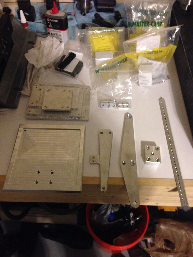
I got a bunch of parts from Scott at benchtopprecision.com today. Part of what I got from him was a belt drive kit, which is awesome. It is a good complete solution.
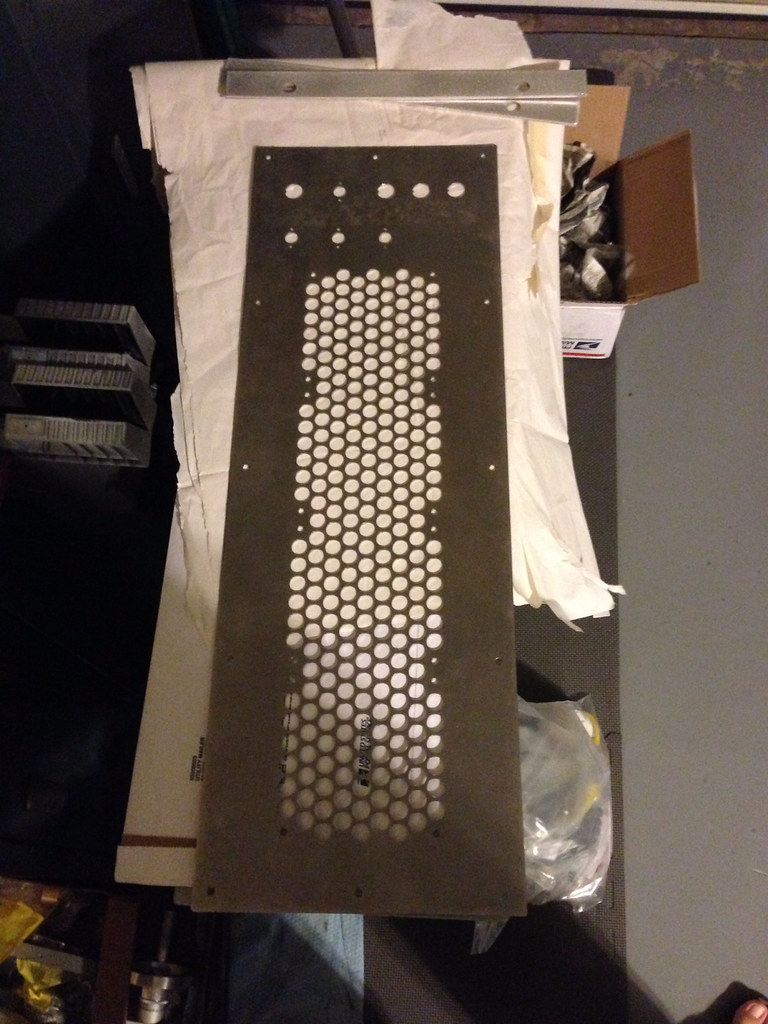
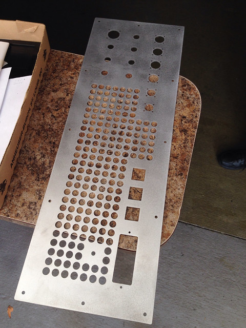
I got the front panel for my electronics enclosure, which I need to powder coat. The front panel only cost me $50 to have it made. I feel like that was supper cheap for the work the sheet metal shop put into it. I was very happy when he gave me the quote. Now all I need to do is finish the rear panel and I can get electronics enclosure put together.
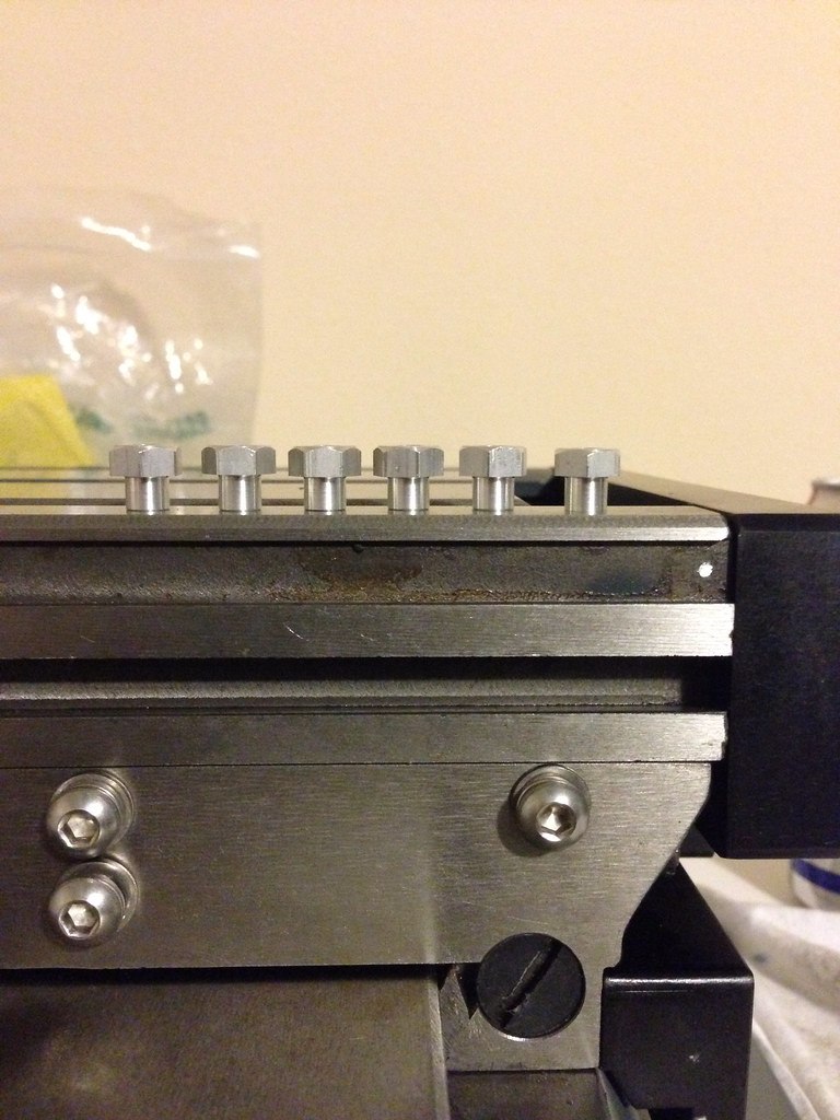
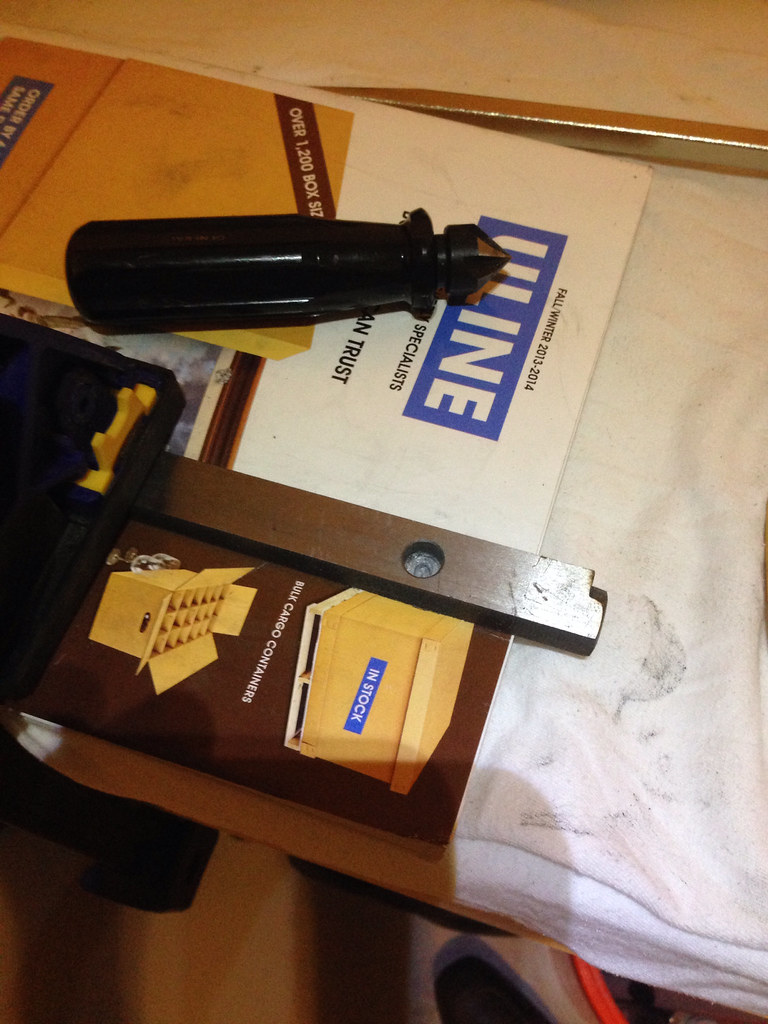
I actually dusted off my lathe and turned down some hex threaded standoffs to make some nuts to retain the bearings for the limit triggers. It felt good to make something I could use. Really looking forward to finishing this mill
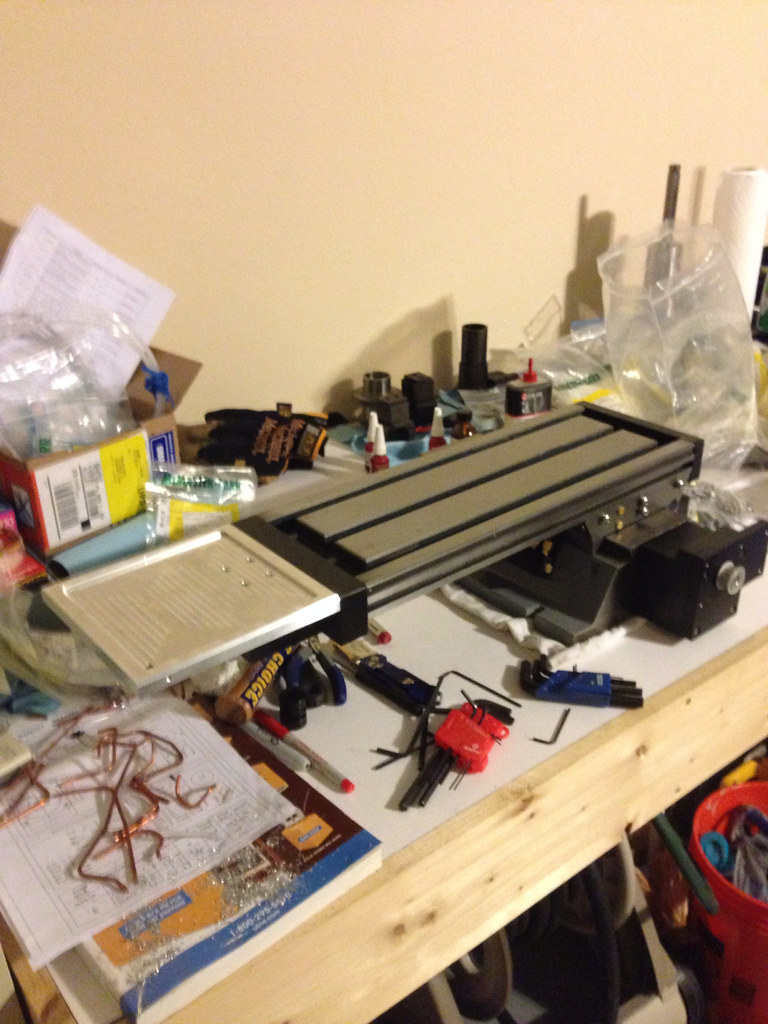
Another thing I worked on is doing the final assembly on the x -axis. This just entailed mounting the left side end plate where I wanted it, loosening the screws that hold the x-axis ball nut and driving the table back and forth with an electric screw driver. This made sure the ball nut was lined up properly. After that I tightened the ball nut down, I drove the table all the way to the left and mounted the right side plate.
Tomorrow I am going to start assembling the z-axis. First thing I am going to do is repack the ball nut and make sure all the balls are there and then drill a hole in the gib strip. With that done, I can get it put together.
So here are the pictures (sorry for the long narrative):
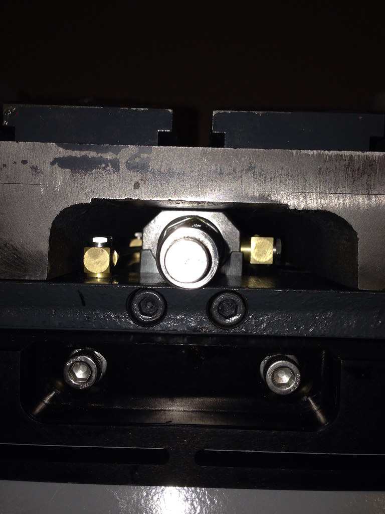
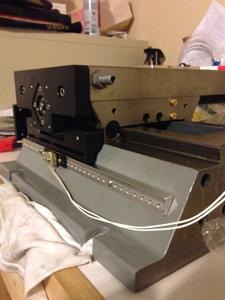
Underneath the saddle right before mounting the right side plate:
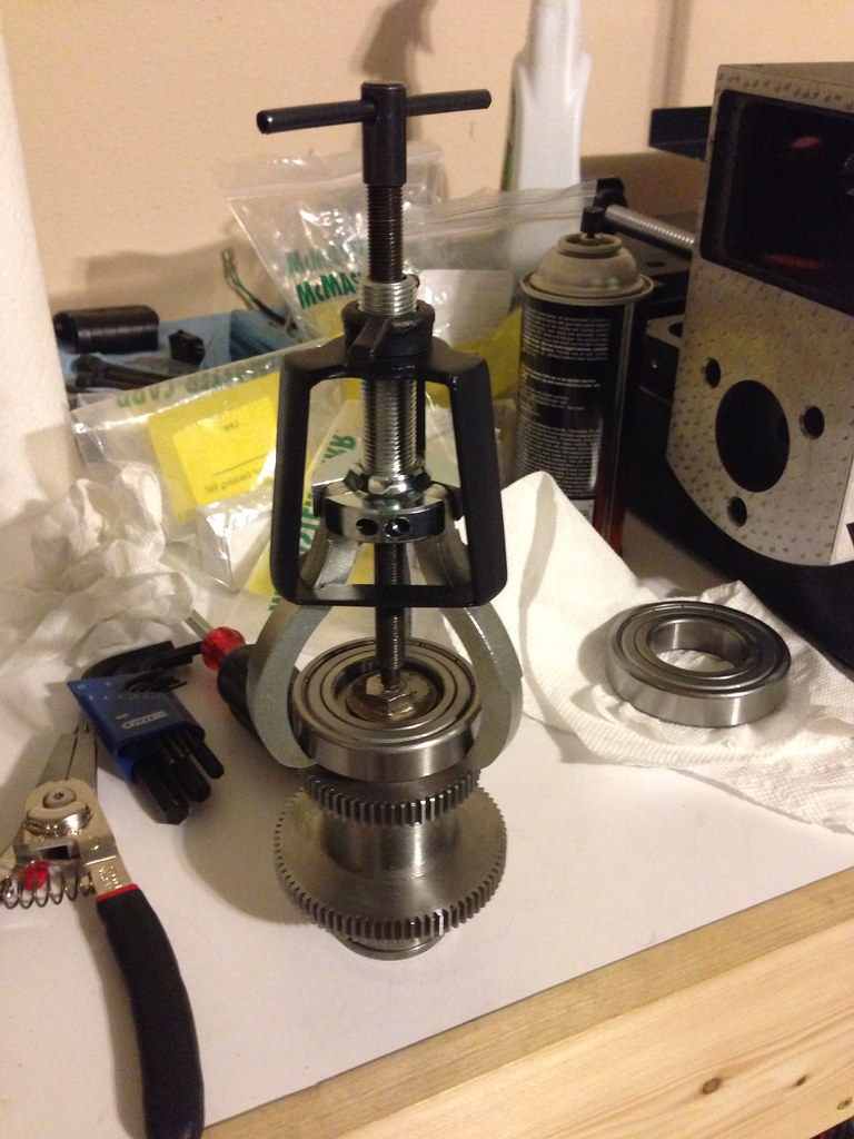
Trying to reuse the bearings…maybe:
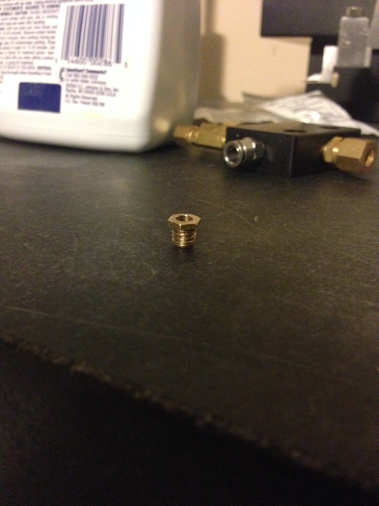
Z-axis manifold with check valves:
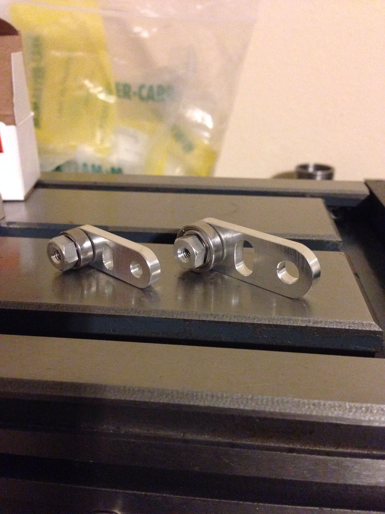
Bearing retaining nuts:
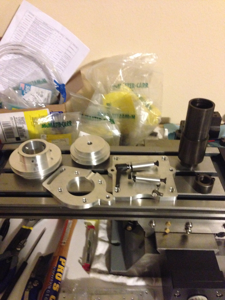
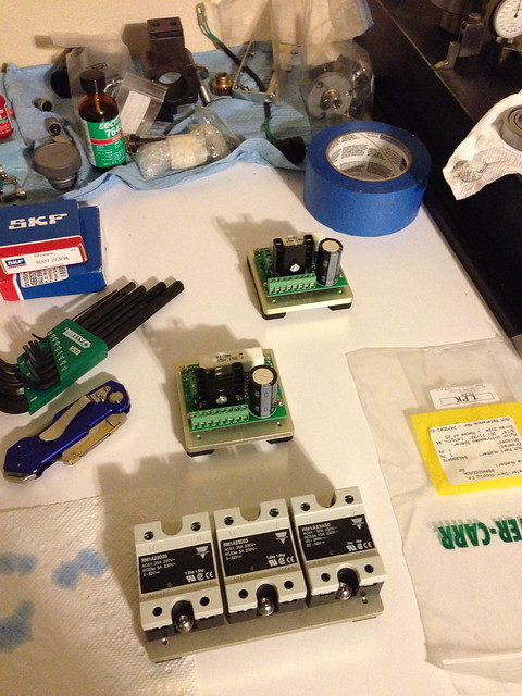
Parts I got from Scott:
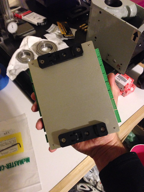
Assembled limit triggers:
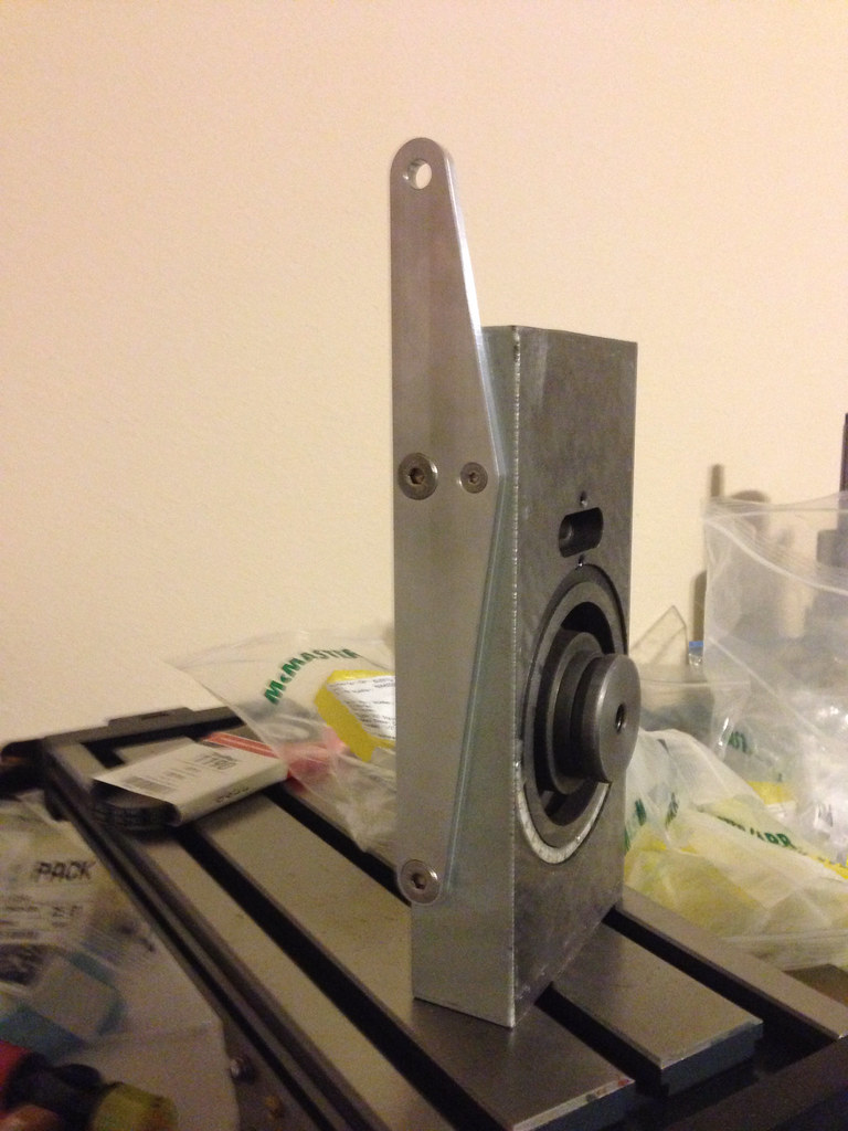
Test fitting the gas shock mount:
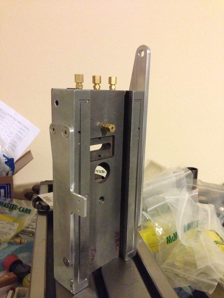
Limit switch mount and oil fitting installed:
X-axis stepper cover mounted (got the idea from Tormach):
Y-axis limit mount:
Front panel to my electronics enclosure:
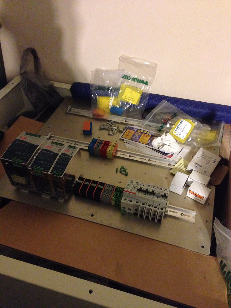
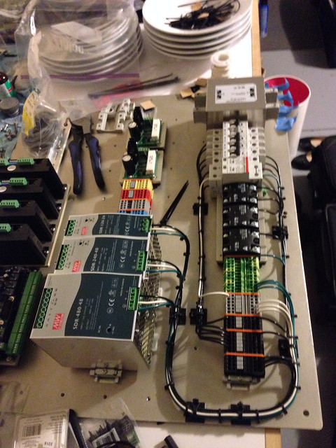
Starting to put together my electronics panel (I made din rail mounting plates for everything):
Belt drive kit from Scott:
Graham, you do very nice work! Excellent craftsmanship.
Looking forward to seeing your build complete.
Really nice update, Graham, it's fun following along watching your progress.
May I ask what the belt drive kit cost?
Thanks for sharing-
Dave
Dave->..
It's nice to see what all these parts are used for, that I've been making over the past year. Some of them were obvious, but others I didn't have a clue. Graham got a discount on the belt drive in exchange for valuable information and feedback.
I don't want to take away from this thread, Graham has a very nice build here, keep it up.
Last edited by ger21; 01-01-2014 at 10:14 AM.
AVRnj thank you very much for the compliment, but I don't think I can call myself a craftsman yet. I have designed all of the parts, but if a part looks like it was made on a mill then Scott at Bench Top Precision made it for me. Hopefully soon I will be able to start making my own parts when the mill is running though
Thanks Dave! I think I am starting to get a little momentum going...starting to see the finish line
Thanks for posting Scott it is good to see you on the build logFeel free to hi-jack the thread, just happy to see some people are following the build.
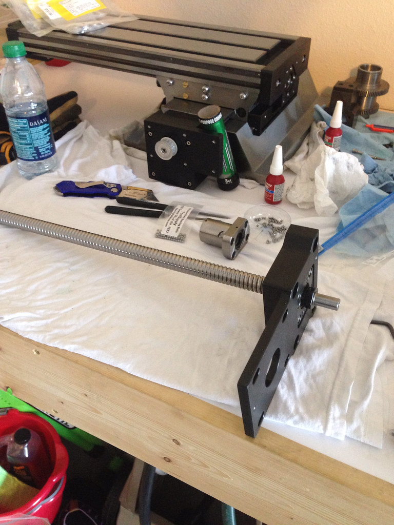
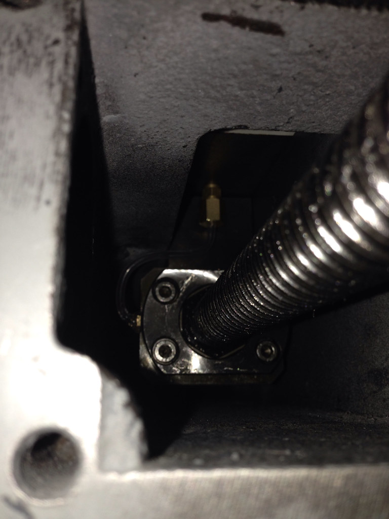
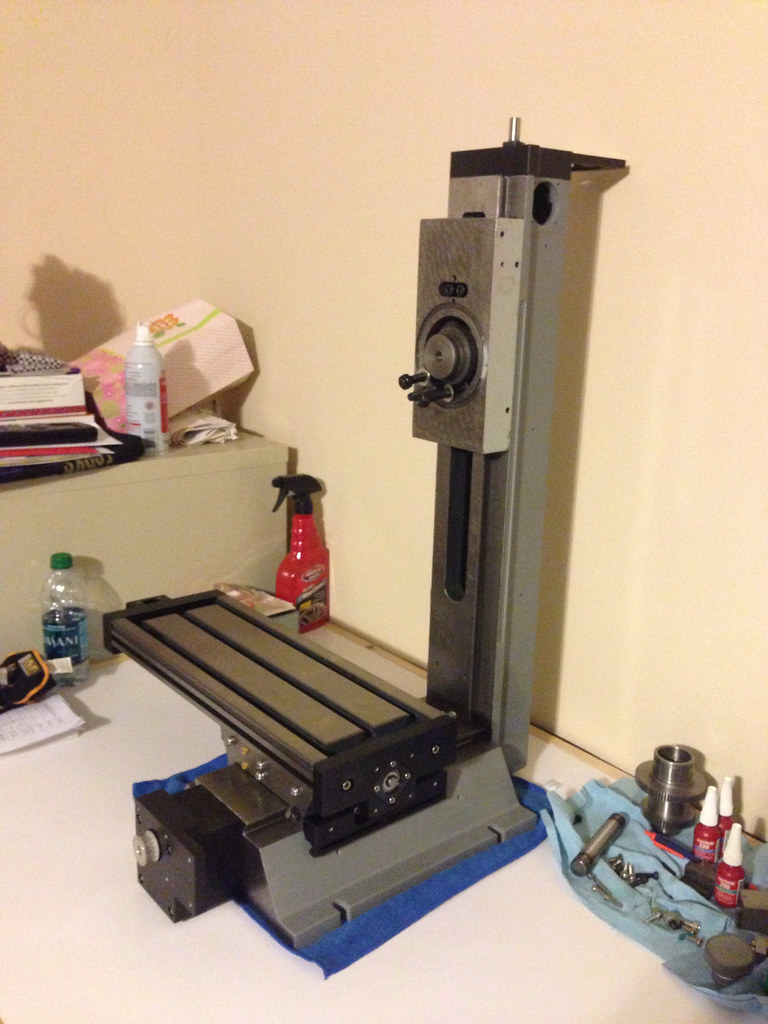
I got the z-axis put together and I got the column mounted to the base. Getting the compression fitting and the oil line ran to the ball nut inside the column was a SOB. I started work on it about 1:00 PM and finished at 3:30 AM, but I got it installed
One concern that I have been wrestling with is how to cover my cables. I bought Amphenol RT360 connectors off of McMaster and was feeling good about what I was doing, but then I started thinking about hot chips eating into my cables over time. I think I have come up with a good solution. I am going to by some continuous-flex nylon conduit off of McMaster and the associated bulk head mount 1/2 NPT fittings, rout the cable through it and then make an aluminum adapter that lets me screw the conduit fitting into the back of it and then screws onto the back of the connector head, so essentially I am making a back shell that lets me make an armored cable. Plus, it is something I can make on my lathe. I am not sure that is easy to follow but when I post up some pictures in 3 or 4 weeks (going out of town) it will make a lot more sense. I am really happy with this solution because it solves my problem and I still get to use the parts I already bought. As Charlie Sheen would say “Winning!”
Another thing I am starting on tonight is the design for parts that go on the head of the mill, which is basically the pneumatic cylinder for the automatic drawbar, the spindle top hat, the drawbar itself, and mounts for everything. I think I am going to buy Hoss's plans and make a hybrid between his cylinder design and another one someone did for an LMS SX2. I think Hoss’s plans are worth it just for his design of the drawbar, which would take me some trial and error to get right. I will be doing the design work at night while I am sitting at the hotel when I am out of town.
One other thing that has turned out really well which I was worried would be a waste of money is the cable routing bar I design that mounts on the back of the mill. It is allowing me to mount a bunch of stuff I had not planned on needing besides just tying the cables to it as they route up the column.
Anyway enough typing, here are some more pictures of the progress:
Drilled my gib strip:
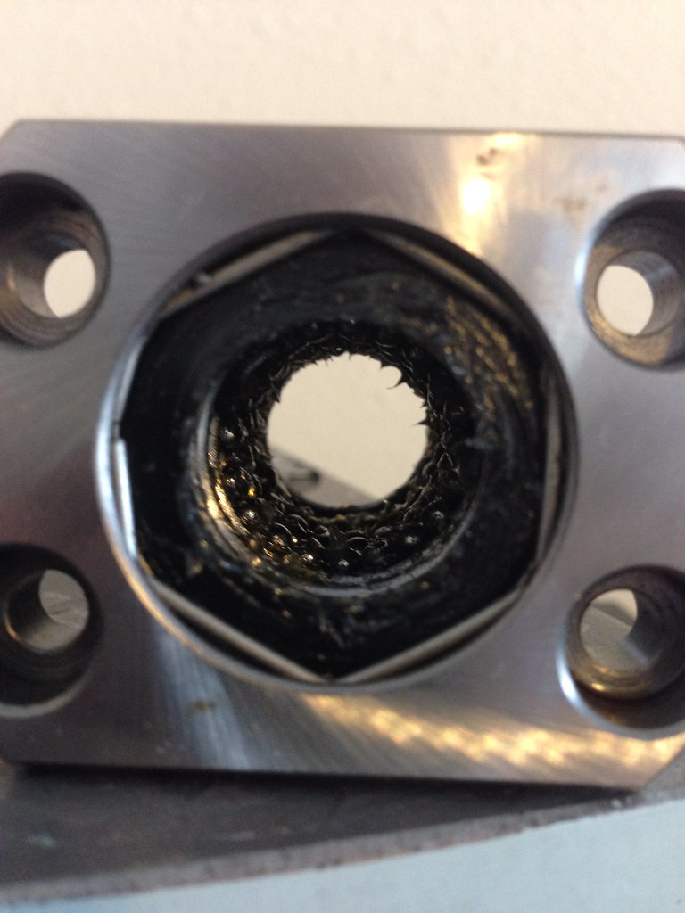
Repacked the ball nut (used grease and a craftsman ice pick like tool):
Ball nut:
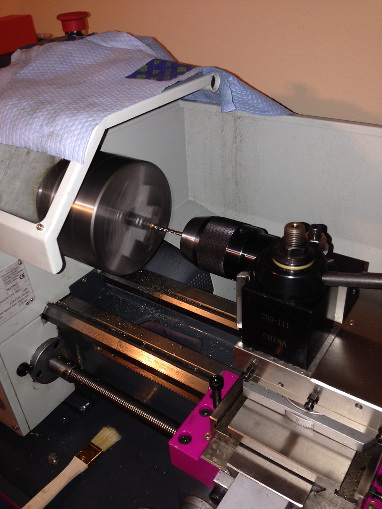
Turning down a zerk fitting:
Finished fitting:
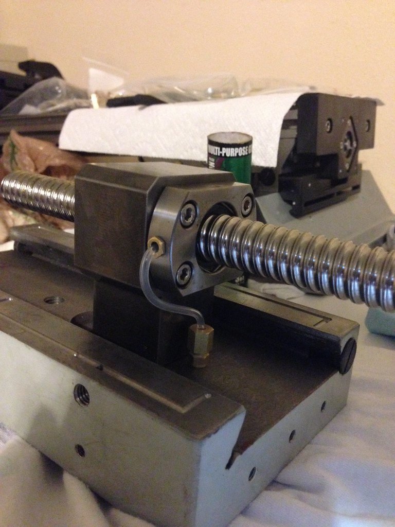
Test fitting everything together:
Everything installed:
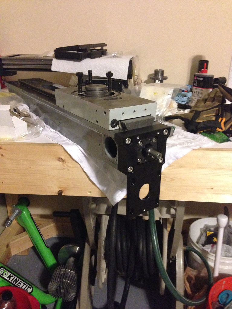
Motor mount installed:
Column mounted:
Last edited by gcofieldd; 01-04-2014 at 02:29 AM.
It has been a long time since I posted any progress, so I thought I would get off of my butt show you what I have been doing, which is really not that much, but I am very close to being able to move the mill around. I think in two to three more weeks I will have everything cabled up and moving. I have powered all of the components and they work as best I can tell. My multimeter crapped out and that was causing me some confusion before I realized it was the meter…I hope; I have not gotten a new one yet. The reason things have taken so long is because money was getting tight and I needed a little break.
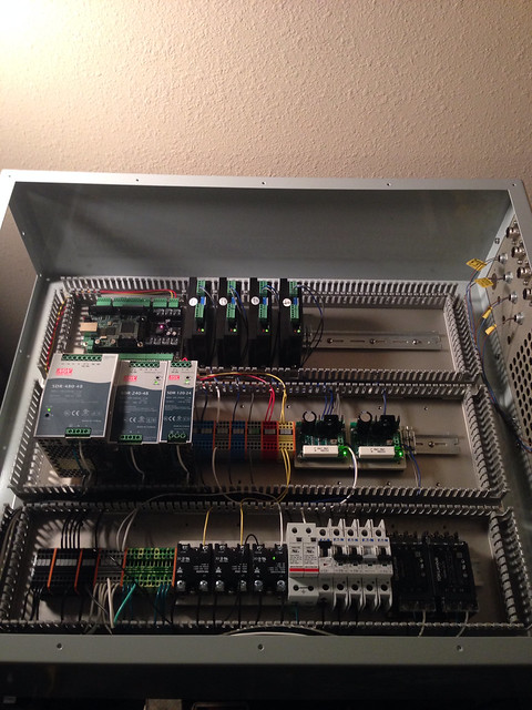
I tried to wire the control box twice. The first time I tried to dress the wires with zip-ties, which was very time consuming and the second time I got some wire duct (1” wide by 1.5” tall). The wire duct is great. If you order any do not get the adhesive backed version because the adhesive strip is tiny and will not hold. I bought double sided foam tape and used that.
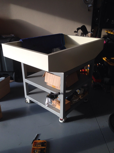
I am not supper happy with everything I have done, namely the way I mounted the mill and the way the coolant drains, but I will see how it plays out. I mounted the mill to a 1 inch thick aluminum plate. The plate is through bolted to the stand with sealing washers on both sides. I also put a rubber sheet between the plate and the tub and a sheet of rubber between the tub and the stand. I put .06” thick shims under the mill so the coolant can drain out if it gets inside the base. I have a 1 inch hole in the tub and the stand which the coolant will drain out of. I hope it will drain fast enough and not clog. I am going to make a flanged tube that mounts in the drain hole so I can direct the coolant into the reservoir.
The last thing I am a little worried about is the wire gauge I have going to my NEMA 34 motor. I am using cable with 20 AWG wire which is rated at 10 Amps per conductor and the connector is rated to 7.5 amps per pin. The spec sheet for the motor says it should only pull 6.1 amps per phase, so it should be ok I guess unless the motor stalls out? I am not sure though, anyone have any thoughts?
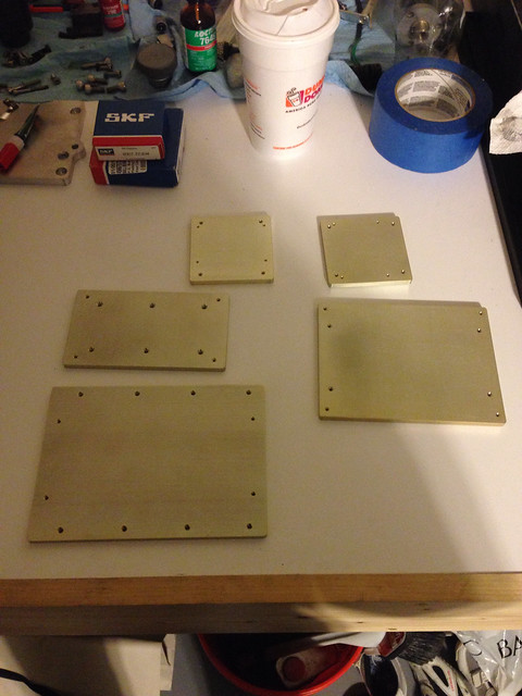
Din rail mounting plates for electronic components:
Mounting clips installed
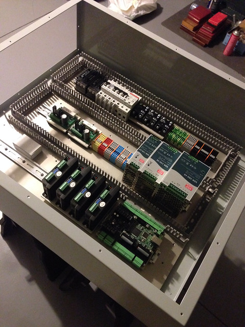
Components mounted
Rear IO of electronics enclosure (after I put in the wire duct I had to flip the panel over so the power entry module would fit)
First attempt at wiring without using wire duct…which sucks
Control box laid out with wire duct
Wiring diagram I am working from…needs to be updated and finished
Control box with 75% of wires installed and components powered up
Oiler Mounted
Gas Shock Mounted
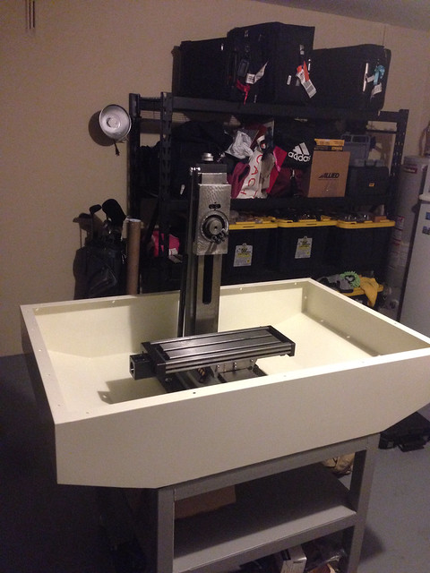
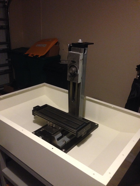
Mill in the Stand 1
Mill in the Stand 2
Where I am heading with the design once I get it running and can make parts
Nice Work,
The steppers will Draw approximately 6A regardless of whether they are stationary, running or stalled. They are constant current devices, so you should be OK.
Cheers,
Peter
-------------------------------------------------
Homann Designs - http://www.homanndesigns.com
Thanks Peter, that is good info. I will keep working with what I have then
Nice electric setup.
Be sure this gas shock able to work in shaft up position (gas leak after some time) or turn it shaft down.
I recognize those parts. Good to see it's all coming together. Nice work.
www.benchtopprecision.com
| BF20/G0704 Belt Drive Kits | X2 Mini-Mill Belt Drive Kits |
Thanks Alex, I will have to check on that, didn't know that could be an issue.
Slowly but surely, I will get there. Then I have to learn how to go from CAD to CAM to the machine
I have your belt drive kit getting anodized. I should have it back this week
 Posting Permissions