Build Thread Ryan's g0704... - Page 10


Page 10 of 15 FirstFirst ... 78910111213 ... LastLast
Results 181 to 200 of 283

Thread: Ryan's g0704...

  1. #181
    Member fretsman's Avatar
    Join Date
    Nov 2007
    Location
    USA
    Posts
    980
    Downloads
    13
    Uploads
    0

    Default

    Very nice, Ryan, thanks for sharing-

    Dave

    Dave->..


  2. #182
    Registered Mad Welder's Avatar
    Join Date
    Jun 2011
    Location
    Ireland
    Posts
    914
    Downloads
    0
    Uploads
    0

    Thumbs up

    The router build looks like another fantastic creation from you and reading your analysis of the KFlop stuff earlier.....well....alas that stuff went straight over my little mind...but again I must say WOW this cnc'd mill build is one freaking excellent build...I'm going to follow you and others and lap my ways....and again Ryan thanks for the explanations and pics..

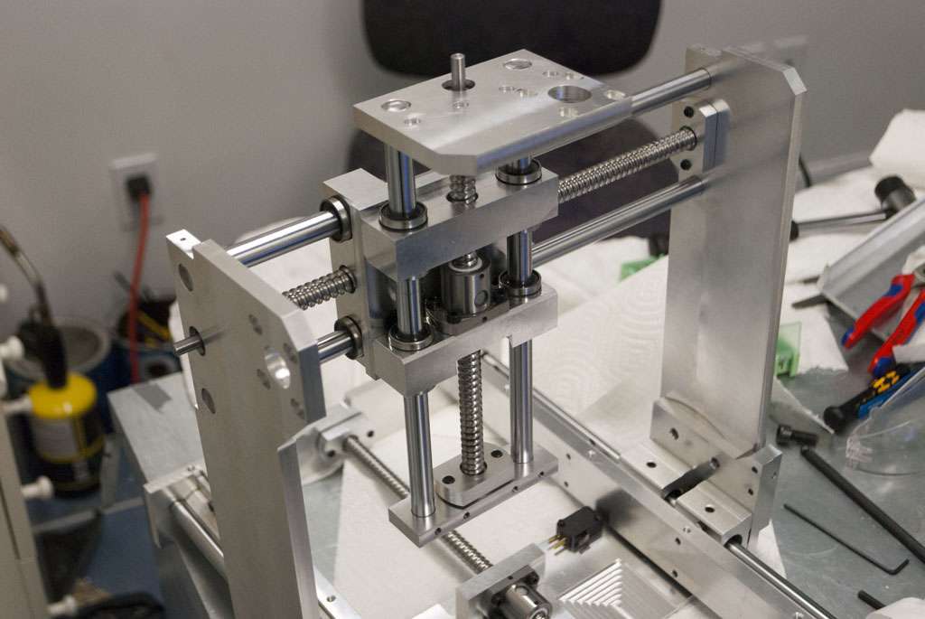
    This build is definitely one of the best builds I've seen well done...and keep the pics flowing for those of us (ME) who find it easier to learn from photos rather than learning from reading ye''re progress. ..

    Eoin


  3. #183
    Registered
    Join Date
    Apr 2005
    Location
    Canada
    Posts
    419
    Downloads
    0
    Uploads
    0

    Default

    I'm liking the machine more and more. I never realized just how much I was missing with the old round-column mill.

    I've started taping a piece of paper to the front of the head to block chips:


    I really like having two vices on the table. I guess for this kind of work you kind of need two.


    Up close there is evidence of vibration in my surface finish (and frankly its pretty easy to feel vibration just by touching the mill head).

    The vibration is present with the empty spindle so it is probably coming from the spindle itself. When I get around to removing the 5th axis and replacing it with a spacer it should clean that up a bit, but I think a machine in this price/weight range is going to be limited.


  4. #184
    Registered
    Join Date
    Apr 2005
    Location
    Canada
    Posts
    419
    Downloads
    0
    Uploads
    0

    Default

    Been working on this all day every day.


    I had no 21mm retaining rings so I press fit the linear bearings.


    The plan...


    I will have to cut the stepper shafts and cut notches in the box so it can fold.


    And just showing how the two nema 14 steppers avoid hitting eachother.

    I had to custom order the nema14s and they are beasts, 2A with 2.5mH inductance. I will be running at 36V with 2:1 reduction so hopefully they will be okay.


  5. #185
    Member Fastest1's Avatar
    Join Date
    Nov 2009
    Location
    USA
    Posts
    4415
    Downloads
    0
    Uploads
    0

    Default

    To add portability to an already beautiful project just puts this over the top. Nice work to say the least.

    A lazy man does it twice.


  6. #186
    Registered BAMCNC.COM's Avatar
    Join Date
    Sep 2012
    Location
    USA
    Posts
    1543
    Downloads
    0
    Uploads
    0

    Default

    Wow.. will you be selling those? I want one!


  7. #187
    Registered
    Join Date
    Feb 2012
    Location
    USA
    Posts
    296
    Downloads
    0
    Uploads
    0

    Default

    The machine looks great! I look forward to seeing what you make with it.

    Do you mind going into a little more detail about what you did with your spindle and why?

    I would greatly appreciate it!

    Thanks.


  8. #188
    Registered
    Join Date
    Apr 2005
    Location
    Canada
    Posts
    419
    Downloads
    0
    Uploads
    0

    Default

    Been a long day and I'm super tired but I'll post a teaser picture. The clearances are hilariously tight, almost every critical piece has 2mm of clearance in the CAD and it seems to work in real life as well.


    Probably too much work went into this guy to make it economical to sell. I can put the CAD files up though.

    DRock: My g0704 spindle has gone through a bearing replacement (exactly as hoss describes). I then mounted a 25 tooth pulley on the spindle and a 50 tooth pulley on a DMM-Tech 1.5KW servo.

    I plan on completely redoing that whole section. When I remove the 5th axis I will put in two sets of timing pulleys for a high and low gear, as well as leave room for a power drawbar and such.

    The servo appears to have more than enough power for the g0704. Have not tried rigid tapping yet but I might need a second encoder directly on the spindle depending on how much the belt stretches.


  9. #189
    Registered
    Join Date
    Apr 2005
    Location
    Canada
    Posts
    419
    Downloads
    0
    Uploads
    0

    Default

    I cut a plexiglass table just for show:


    The table is about 12x18 which is too large for me to really handle myself. I ended up getting it waterjetted by a local machine shop. They charged me 73$ for the job which is actually less than I would have spent on a similar piece of plate.

    I'll still need to tap and counterbore the holes, and I'll run a facemill over the top as well.


    Working on mounting the electronics:


    And the current state of things. Excuse the poor pictures, I had horrible lighting:


    Still a fair deal of work to be done, the electronics are not entirely finished and I need to fully enclose them as well to prevent chips from causing problems. Also need to build a spindle.

    The case weighs about 42lb with the aluminium table. Pretty damn heavy, but still "portable".


  10. #190
    Registered
    Join Date
    Feb 2012
    Location
    USA
    Posts
    234
    Downloads
    0
    Uploads
    0

    Default

    I want one!!!!! its like 007 meets machinist with a little bit of thomas crown affair. great work.


  11. #191
    Registered
    Join Date
    Jan 2006
    Location
    usa
    Posts
    115
    Downloads
    0
    Uploads
    0

    Default

    007, I was thinking the same thing. Maybe something that Q carries into the field to fix stuff that Commander Bond breaks.


  12. #192
    Member
    Join Date
    Dec 2012
    Location
    Norway
    Posts
    390
    Downloads
    0
    Uploads
    0

    Default

    What are the various electronic boards? I see a Kflop and what looks like a driver board with 4 Polulu drivers (3 with heatsink), but what are the other boards for?


  13. #193
    Registered
    Join Date
    Feb 2006
    Location
    us
    Posts
    1187
    Downloads
    0
    Uploads
    0

    Default

    man I tell ya what people just amaze me!! Beautiful work Ryan !!!!


  14. #194
    Registered
    Join Date
    Apr 2005
    Location
    Canada
    Posts
    419
    Downloads
    0
    Uploads
    0

    Default

    Main board is a KFlop, then there are 4 "breakout" boards, all just wires on protoboard.

    As you noticed, the red board has slots for 4 pololu drivers for axes XYZA. The green board handles home/limit switches, the white board handles the control panel, and finally the blue board just connects everything to the KFlop.

    I'm having a bit of trouble with wire management, I'm not entirely sure how I will get power to the steppers in a way that folds up easily and stays out of the way in use. Unfortunately, there isn't room for cable chain.

    The only option I can come up with is just having a few feet of cable going to each stepper and just watching so it doesn't get caught.


  15. #195
    Registered Mad Welder's Avatar
    Join Date
    Jun 2011
    Location
    Ireland
    Posts
    914
    Downloads
    0
    Uploads
    0

    Default

    Flippin heck that really is an outstanding build Ryan and as you said earlier...all in a flight case....


    Quote Originally Posted by punisher454 View Post
    007, I was thinking the same thing. Maybe something that Q carries into the field to fix stuff that Commander Bond breaks.
    I'd love to see the face on the chap at airport security when you plonk that thing on the x-ray conveyor belt

    Eoin


  16. #196
    Registered
    Join Date
    Apr 2005
    Location
    Canada
    Posts
    419
    Downloads
    0
    Uploads
    0

    Default

    Finally got my hands on a camera again. All the electronics have been finished and tested, I was just waiting on some high-flex cable to connect the steppers. The cable arrived today and the mill should be moving in a few hours.

    The spindle is mostly finished, I need to mount it to the mill and make the pulleys.

    The spindle is essentially a direct clone of matec54's build here:
    http://www.cnczone.com/forums/cnc_wo...dle_build.html

    I made some changes to the design since I am not using a matched pair of bearings so my nuts lock like the ones on a g0704 spindle.

    The spindle is aluminium and uses a preloaded AC pair of bearings at the front, and a deep groove bearing at the back preloaded by a spring washer. It uses an ER8 collet chuck. The motor is a 400W hobby brushless and I plan on hitting 16K -20K RPM.


    There should be enough room for the wires when the mill is folded, but it will take a bit of work to make sure the wires dont get caught or crushed while the box closes.
    The blue tube is for compressed air. I have a solenoid with the electronics so I am hoping to have air blast cooling to keep chips from building up.

    You can see a lot of cracking in the acrylic sheet in the photos. I will have to redo it in lexan or aluminium.


  17. #197
    Registered zamazz's Avatar
    Join Date
    Jan 2013
    Location
    US
    Posts
    164
    Downloads
    0
    Uploads
    0

    Default

    That little machine is beautiful! I particularly like those lighted buttons! Do you mind telling me where you got those?


  18. #198
    Registered
    Join Date
    Apr 2005
    Location
    Canada
    Posts
    419
    Downloads
    0
    Uploads
    0

    Default

    Quote Originally Posted by zamazz View Post
    That little machine is beautiful! I particularly like those lighted buttons! Do you mind telling me where you got those?
    They are 19mm vandal switches. You can get them off ebay by searching "19mm switch":
    19mm switch | eBay

    Pricing varies a lot, and sometimes a certain color will be way cheaper than others. If you pop the switches open you can change the LED, it takes about half an hour.

    I bought a pair of yellow switches and put in RGB leds so both switches are full RGB and change color depending on what the mill is doing.

    You can also get them larger/smaller (21mm, 16mm...) but I've found that 16mm is uncomfortably small and hard to press.


  19. #199
    Registered zamazz's Avatar
    Join Date
    Jan 2013
    Location
    US
    Posts
    164
    Downloads
    0
    Uploads
    0

    Default

    Awesome. I think I'll pick some of those up for my machine.


  20. #200
    Registered Mad Welder's Avatar
    Join Date
    Jun 2011
    Location
    Ireland
    Posts
    914
    Downloads
    0
    Uploads
    0

    Default

    Quote Originally Posted by zamazz View Post
    That little machine is beautiful! I particularly like those lighted buttons! Do you mind telling me where you got those?
    Illuminated Pushbuttons, Poker VLT Buttons, Replacement Button Sets, LED Lamps and Custom Artwork

    Here's another source....didn't check the price difference from ebay but the rectangular smallto medium sized look good.

    Eoin


Page 10 of 15 FirstFirst ... 78910111213 ... LastLast

Tags for this Thread

Posting Permissions

  • You may not post new threads
  • You may not post replies
  • You may not post attachments
  • You may not edit your posts
  •  


About CNCzone.com

    We are the largest and most active discussion forum for manufacturing industry. The site is 100% free to join and use, so join today!

Follow us on


Our Brands

Ryan's g0704...

Ryan's g0704...