
 Reply with Quote
Any plans for lighting inside the enclosure? LED perhaps?


The sheet metal machine is a 3 in 1 equivalent to this machine: Grizzly.com
I wasn't particularly excited about using a 3 in 1, but it has performed fairly well for its cost. I've never used the slip rolls but the shear/bender work as advertised. I've bent 18ga mild and 20ga stainless 30" wide. You have to apply a ridiculous amount of force, but the sheet metal bends before the machine breaks.
Unfortunately I don't have many pictures of it in use, and I'm essentially done with all the sheet metal at this point. The best I've got is a post for the control panel: http://www.cnczone.com/forums/bencht...ml#post1353674
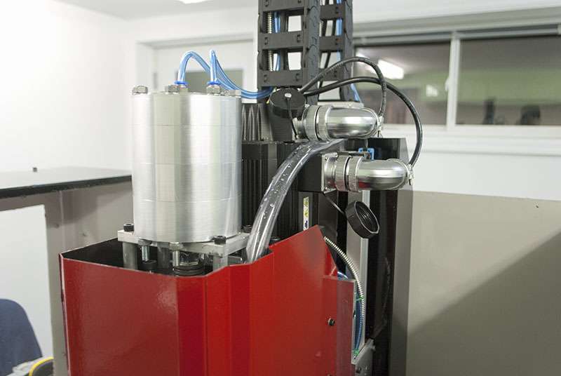
I haven't had time to do much more work, but I've been playing with the cylinder/servo on the head. It will probably end up looking something like this.
I might extend the quill down half an inch or so, so that the air cylinder doesn't stick out as much. I had to move the cable chain about an inch as well to make room for everything. The cylinder is 4" in diameter and the servo is a 5" square so together they take a fair deal of space.
Any plans for lighting inside the enclosure? LED perhaps?
I have purchased an LED ring for the spindle. I expect that will be enough lighting, but I also have a few meters of white LED strips if necessary. I have four 12V relay outputs right now, I've budgeted one for PDB, one for coolant, one for ATC and one for lighting.
If I need air blast to keep chips out of the ATC I will probably wire that in with the PDB. If anyone knows anything about that it would be great, because I'm not actually sure where the air is supposed to be blasted.
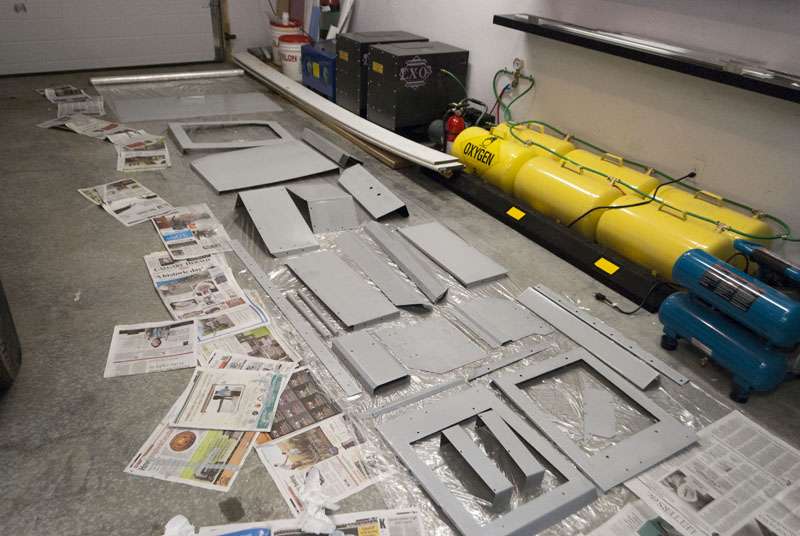
Here is a completely unrelated project that I've been working on. I am building a pair of kilns, and decided to try shopping out the sheet metal work. I did the CAD and they made the parts.
They did a really good job and everything fits and looks great. I'll need my mill to finish them up though.
Anyway, I pretty much just painted the sheet metal and did some small tasks.
I glued in the drains, they are 3/4" ID.
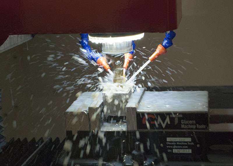
Here are the coolant nozzles.
The fit and finish isn't perfect but it gets the job done.
I kind of want to build an 8x4 plasma/router table now, but that will probably be another project that never gets completed.
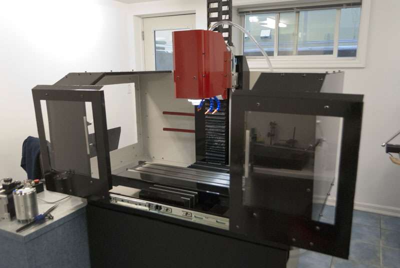
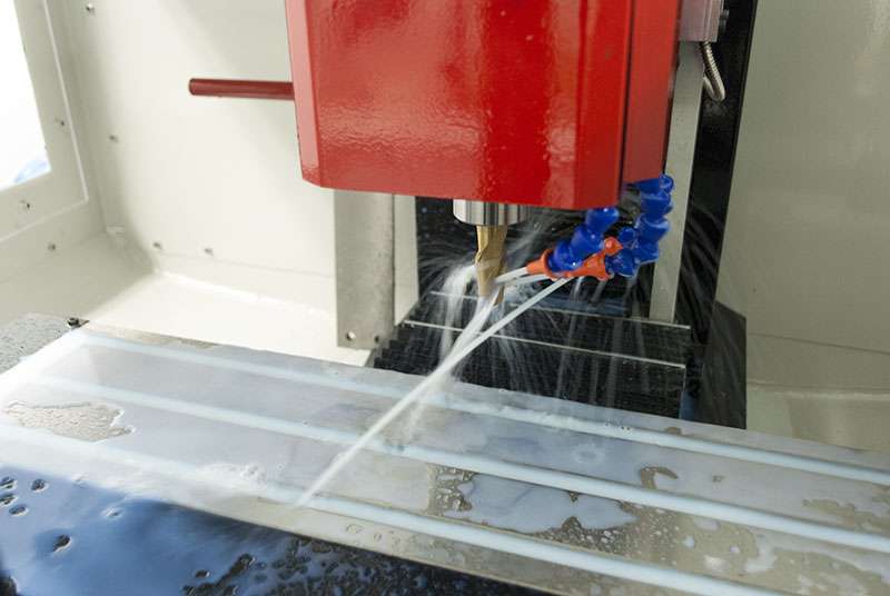
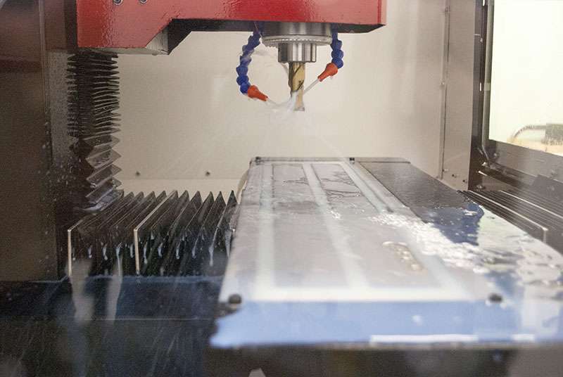
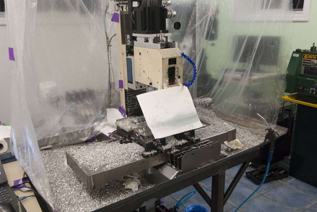
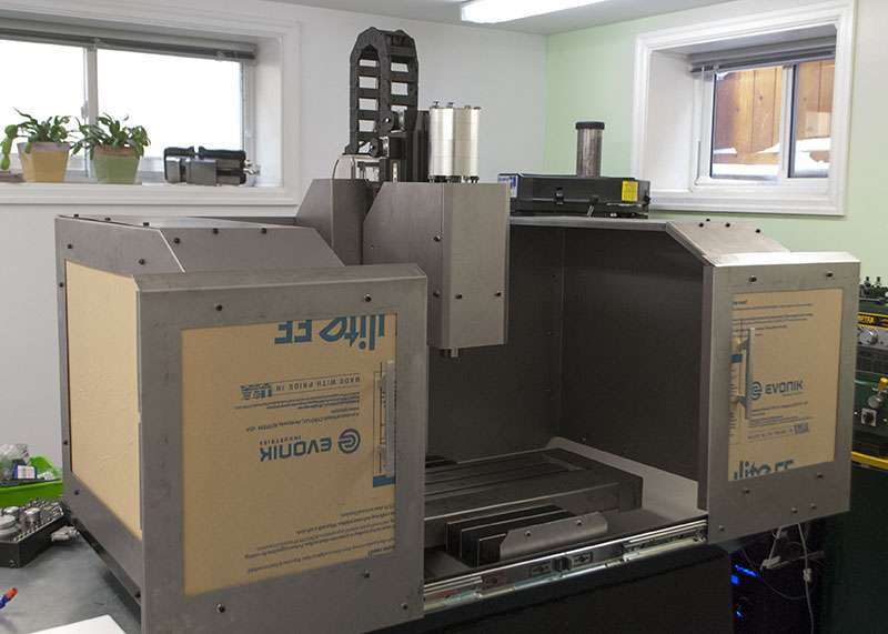
Finished up the head and the flood.
This has the 3 stage air cylinder as well as a 1.5KW DMM servo running the spindle. So far everything seems to work.
The flood coolant is fairly satisfactory as well. So far no leaks, although the sheer volume of coolant floods over the table and works its way onto the Y axis.
Everything has been tested individually, but I still have to wire up the solenoid/SSR and write some code.
The pump is 400GPH off ebay and it moves a ridiculous amount of liquid given its size.
I decided to bite the bullet and picked novamet 872 as the coolant ( NOVAMET® 872 - coolants from Oemeta ). The smallest container (5 gal) was 130$, but I figure that having something that wont rot, stain or rust is probably worth it. It will probably last me a decade or two as well.
I finished wiring and coding the power drawbar and flood coolant. The power drawbar cannot be enabled while the spindle is moving.
I forgot to seal the holes that allow the mill to be bolted to the stand, so there was a bit of leakage through the washers/threads there. I'm waiting for the silicone to dry before making test cuts, and I also need to break in the spindle (I assume I should break it in again since its been sitting for so long).
That essentially puts me at the point where I need to pick up some Tormach tooling but its looking like a pretty hefty expenditure.
Anyone have an opinion on the surface plate+height gauge combo ( 31713 - Small Granite Surface Plate with Integrated Tool Hole ) as compared to a Z axis setter ( shars.com - Precision Magnetic Z Axis Setter 2quot Height x 0001quot )?
I feel like being able to set the tool table without having to load and touch off a dozen times in the mill is worth an extra 120$.
I ended up doing the very first test cut today.
I didn't want to swap out R8 collets, so I had to use my only 3/4" endmill. It is in horrible shape since its an import and I used it for all the cast iron/steel while building my g0704.
I went about 2mm deep but the machine seems to do well.
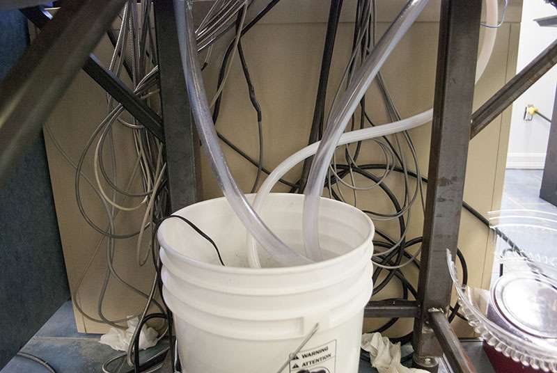
Here is a picture of the flood setup, just a 5 gallon bucket.
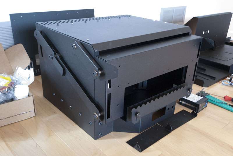
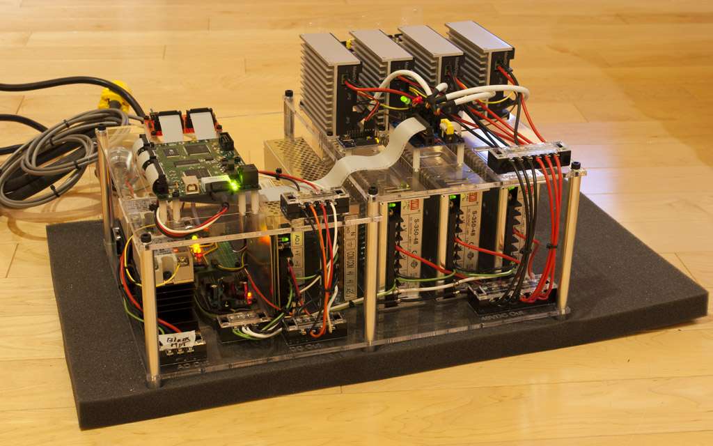
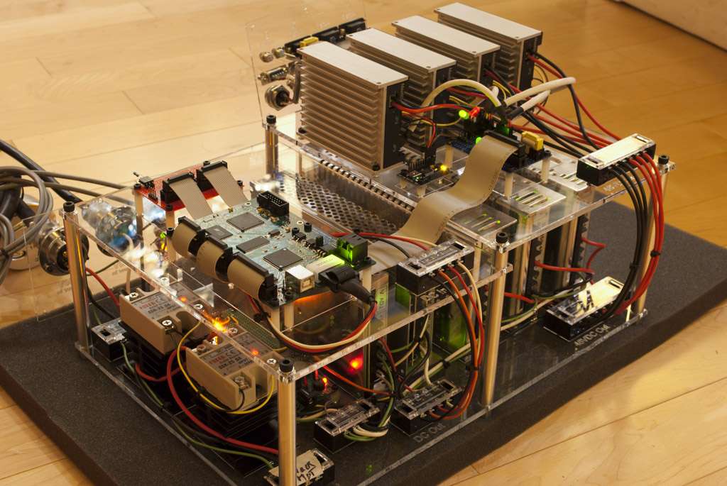
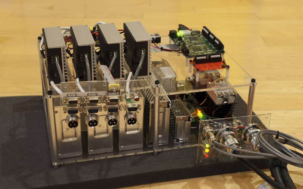
I'm kind of mixed on my decision to house the electronics in a separate box and to use standard connectors for every connection. Its convenient in a way, but it also leads to this mess. Frankly, I can't really think of a situation where I would want to disconnect the electronics from the machine so it would have probably been better off attached in some way to the machine so that all the wires could be cut to length.
You can buy tts compatible holders on eBay for a quarter to a third of the price of the genuine Tormach ones. The quality is very good.
Search for "c3/4 ER"
Install the easiest connectors to disassemble. Though you dont see it now, there will be a time when a tear down is essential, preparing now will eliminate headaches later.
Dont put the electronics below the working environment of a machine using full flood. You might get lucky and never have a leak, most likely you will have a leak and ruin some good equipment and endanger yourself.
No video of the 1st cut?
Two more tasks have come up, but other that that it seems like the mill is completely finished.
I need to retram the head since the addition of a motor/pdb has changed the alignment; and I need to make a small sleeve to keep the drawbar centered, as right now it is way off and creates vibration.
Unfortunately only my cellphone can take video, but here are two quick clips of the machine. I'll put it through some real testing once I have TTS and some toolpaths.
Test Cut:
Homing:
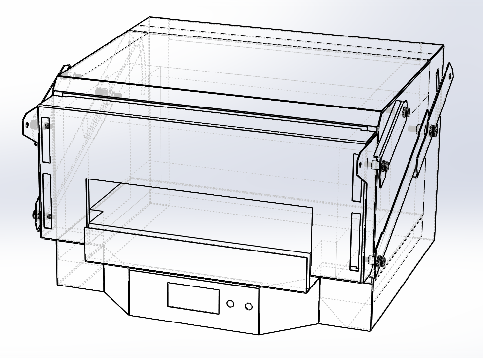
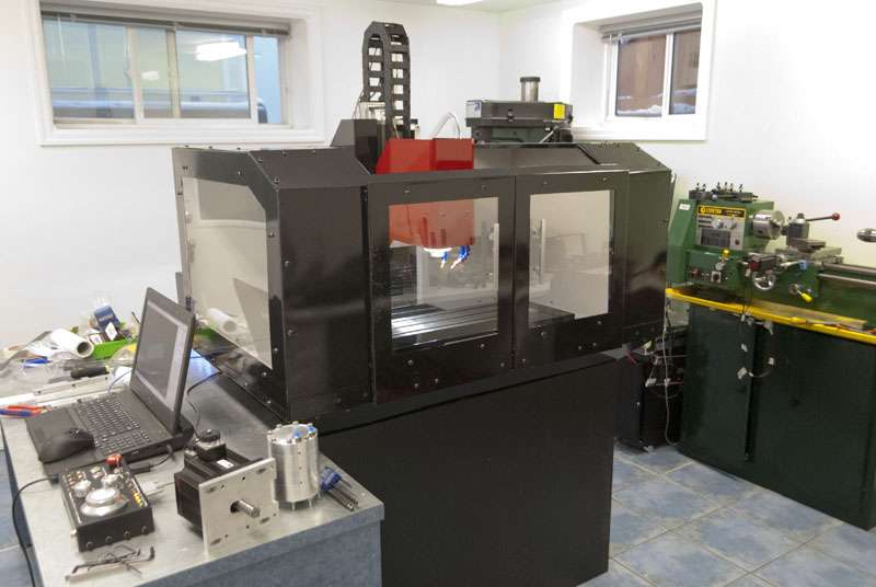
All the recent work has been cosmetic/convenience, so it's still pretty much the same machine it was 8 pages ago, just prettier:
It looks like some of the third party TTS holders have slightly different geometry which might interfere with a potential ATC build. I want to keep that option open so I'll stick to the real thing.
My initial impression of flood coolant has been positive, it is much quieter and has substantial coverage so I won't need to play around with the nozzles between tool changes. So far the coolant stays inside the enclosure, save for a few drips when opening and closing the doors. I don't know whether it will be enough to keep a facemill contained though.
Just an option, eth eBay seller that makes the tts compatible holders does make atc geometry holders, which I believe are fully compatible with Tormach atc. You have to message him and ask.
Got the TTS today, I didn't buy much.
Right now I have 1/2", 3/8", 1/4" and 1/8" endmills in the holders, as well as a probe and two drill chucks.
I thoroughly tested probing today and it works properly. The 2010 screenset has a very comprehensive set of probing routines.
I'll need to set up the tool table and measure all my offsets, then make sure my CAM is set up properly for mach3.
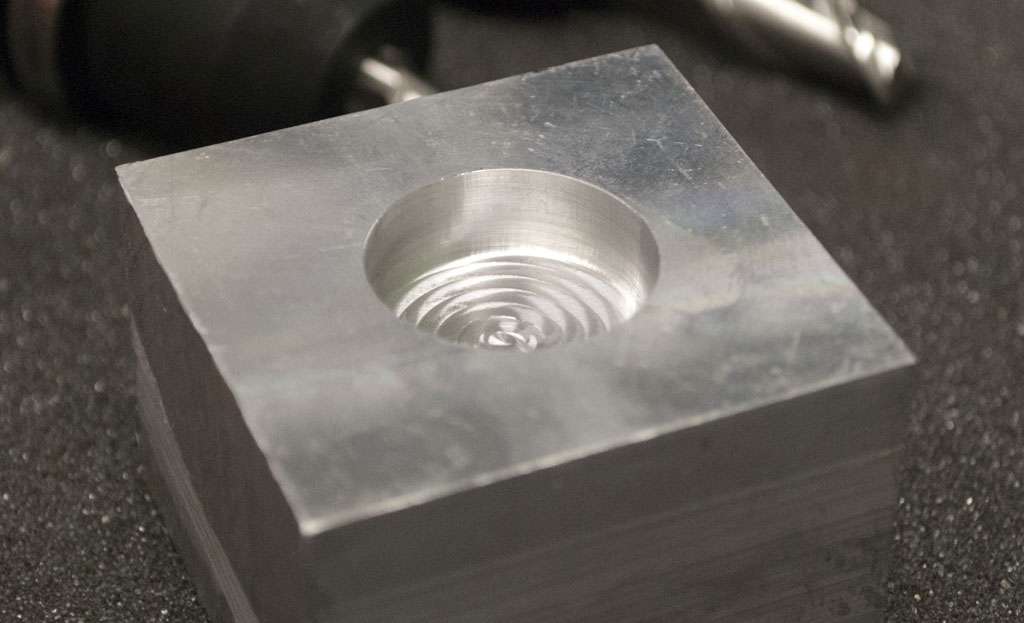
Did a circle pocket using the mach3 wizard just to make sure everything looked okay. 1" dia, 0.4" deep done with a 0.25" endmill, 30% stepover, 0.2" deep per step. 5000RPM 10IPM. A very conservative cut, but the pocketing wizard has straight plunge into 100% engagement entry.
The surface finish is unchanged at the axis direction changes so the backlash compensation via scales/dual ballnuts is working properly.
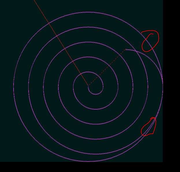
The pocket is not actually a circle due to endmill deflection. It is a few thou small at the bottom, and since the "finishing pass" taken by the wizard has an uneven radial engagement, the circle is out around +-0.003"
The top red circle in this picture shows an area where the tool is cutting the finishing pass at full engagement, and therefore deflecting slightly away from the metal (and cutting a smaller circle).
In the bottom circle, the tool is taking a very shallow cut and is therefore not deflecting much, and cutting a few thou wider.
I can do a lot better with a proper finishing pass (climb mill, very small engagement) but I still don't have my CAM set up.
Well I tried to run a more complex part today and didn't have much fun.
First issue is that two 0.75" drains are not enough, and once chips start piling up the pump is moving more liquid than can be drained. I wasn't paying attention to the coolant level in the tray and it ended up reaching some of the fasteners and leaked all over the floor.
Second issue is that something is wrong with my Mach3 + KFlop setup and it repeatably dies after running ~2500 lines of gcode. The exact point varies by file, but for each individual file it will always stop on the same line. KMotionCNC alone works fine, as does Mach3 in parallel port mode.
And just ensure my day was ruined, Mach3 zeroed all my work offsets.
I just had an endmill pull out near the end of a 6 hour part.
On the plus side the mill works.
Hi Ryan,
I'm just in the process of putting together my power supply and was loving the look of your setup.
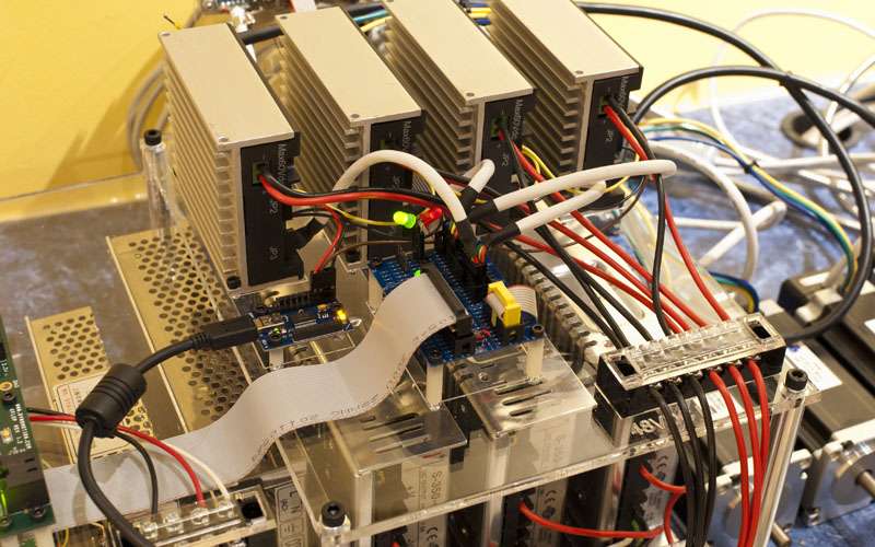
I was wondering where the power for the control lines to the solidstate relays comes from and also what the purpose of the circuit board with the caps on it is used for?
There is a separate, small 5V supply used to power the SSRs. The board with a bunch of caps is just a 3.3V regulator for the KFlop.
Originally Posted by 691175002

Hi, I just received my DMM servo kit and I was wondering how you connected LEDs for Enable and Fault. Do you have LEDs for each axis? I would like to have them as a quick visual when I get my mill set up and start tuning everything.
Your set up looks great BTW!
Thanks
Shaun
my x2 conversion ------> http://www.cnczone.com/forums/showthread.php?t=36403
What brand replacement spindle bearings did you use?
Nice build. Are you running any kind of chip filter for your flood coolant? Can the chips drain to the coolant tank?
What are your plans for the drain situation? You can either add an extra one on each side , don't know if you have one on each side or not , or just tear that one out and add a bigger one. I went with 2 small drains as well on my initial enclosure, one on each side, but I had a little pump so it was enough. When I upgrade my pump, I also had to enlarge the drains unfortunately, but that what we get for going too small to start.
Sent from my XT907 using Tapatalk