Build Thread PM-45 CNC Conversion (RF45) - Page 3


Page 3 of 44 FirstFirst 12345613 ... LastLast
Results 41 to 60 of 866

Thread: PM-45 CNC Conversion (RF45)

  1. #41
    Registered
    Join Date
    Jan 2011
    Location
    USA
    Posts
    385
    Downloads
    0
    Uploads
    0

    Default

    I luckily have a 4 channel lap scope. I used to use it for automotive diagnostic work but the past year I think I've pulled it out maybe 2x because now I don't really ever need a scope to find out of a part is bad. I'm guessing a scope really helps with servo tuning. I thought everyone was using some built in scope function for tuning.


  2. #42
    Registered jid2's Avatar
    Join Date
    Feb 2011
    Location
    Auburn, WA - USA
    Posts
    605
    Downloads
    0
    Uploads
    0

    Default

    No work on the mill itself this weekend. But I built a workbench extension on the side of the garage with the lathe so I could put my baby drill press, grinder and sander someplace. I also did all the wiring for both machines.

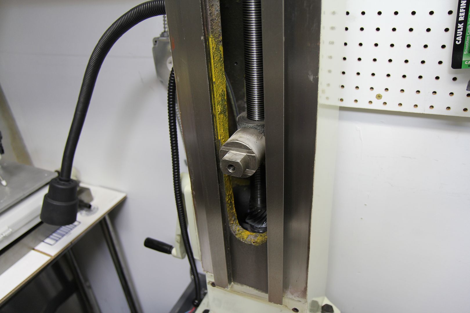
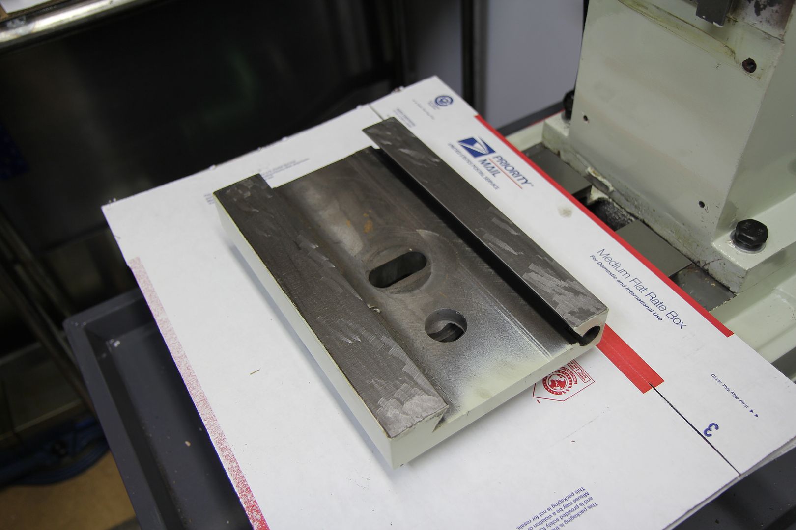
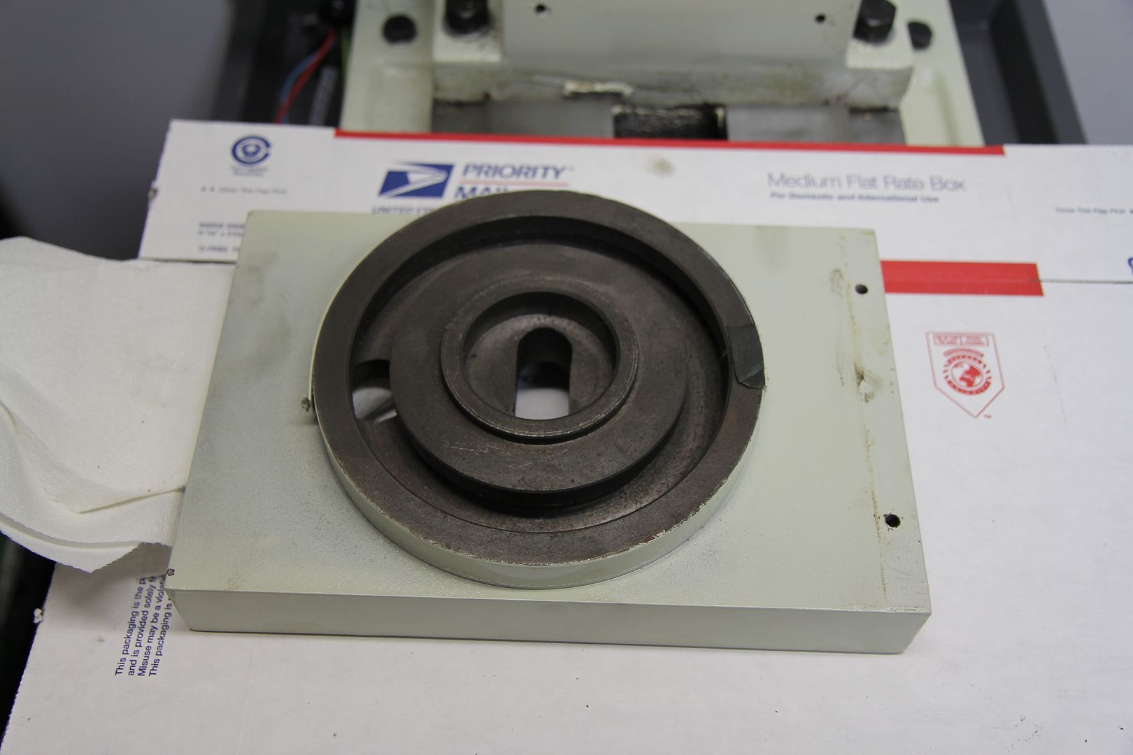
    Next up is to measure the parts of the mill and create the CAD models of everything, then start cutting some oil channels in saddles and such. Gonna have to do that at a friends place.

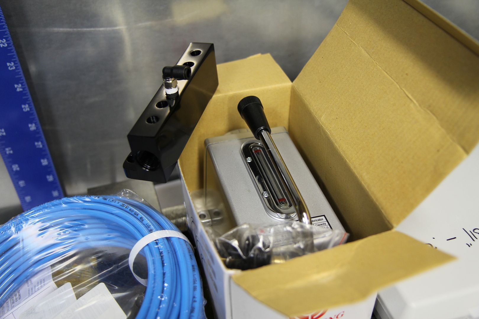
    Just ordered the one-shot pump and a 6 port vacuum manifold block to use as the distributor for the X and Y stuff.

    Last edited by jid2; 02-28-2011 at 01:43 PM.
    PM-45 CNC conversion built/run/sold.


  3. #43
    Registered jid2's Avatar
    Join Date
    Feb 2011
    Location
    Auburn, WA - USA
    Posts
    605
    Downloads
    0
    Uploads
    0

    Default

    Not much has happened lately. All my electrical parts have been sitting on a large commons area conference table at work for about 3 weeks now. Been too busy to actually do any work on it. That's changed though. I gave 2 weeks notice at my current work, as I've found a cooler place. So now I have a deadline to finish the control system before I leave. The office I'm at will likely be closing in a few months so all the other engineers spend a fair amount of time sitting around BS'ing with me as I put this thing together. I'll snap some photos of it tomorrow. It's been a tight fit getting everything into a regular size computer case, but I'm almost there now.

    Getting ready to go machine the saddles for the oil channels at a buddies this Friday. I noticed that the Z axis mounting system is different on the PM45. Here are some pictures, it looks like a more robust design then some of the others out there. I will likely just leave it as-is and build a new Z-Axis mounting block, and not bother with the "plug" concept.


    Here's the pump, fittings, and manifold.


    PM-45 CNC conversion built/run/sold.


  4. #44
    Registered jid2's Avatar
    Join Date
    Feb 2011
    Location
    Auburn, WA - USA
    Posts
    605
    Downloads
    0
    Uploads
    0

    Default

    Control box is just about done. Just need to finish the wiring of the smooth stepper break out and figure out some connectors for the servo motors. I'll fire it up with them hard wired for now. I don't want to use the IEC power entry modules as it's just too easy for someone to plug AC power directly into the Geckos.


    PM-45 CNC conversion built/run/sold.


  5. #45
    Registered
    Join Date
    Jan 2011
    Location
    USA
    Posts
    385
    Downloads
    0
    Uploads
    0

    Default

    Looks pretty sweet.

    Jeremiah
    PM45 CNC Build in Progress


  6. #46
    Registered jid2's Avatar
    Join Date
    Feb 2011
    Location
    Auburn, WA - USA
    Posts
    605
    Downloads
    0
    Uploads
    0

    Default

    OK - I'm having the error with the Geckos not clearing the ERR via the C11T board. I have a couple questions.

    - What makes the decision between using Ground or +5V for the S/D Common pin on the Geckos? Right now I have the C11T jumper set to Ground.

    - I have the Charge Pump feature on the C11T disabled to take it out of the loop.

    PM-45 CNC conversion built/run/sold.


  7. #47
    Member Bubba's Avatar
    Join Date
    Mar 2004
    Location
    lagrange
    Posts
    1806
    Downloads
    27
    Uploads
    0

    Default

    Depends on which Geckos you have. For instance, the 201 etc requires +5 as common.

    Read your manual for the drive that you have. It will tell you.

    Art
    AKA Country Bubba (Older Than Dirt)


  8. #48
    Registered jid2's Avatar
    Join Date
    Feb 2011
    Location
    Auburn, WA - USA
    Posts
    605
    Downloads
    0
    Uploads
    0

    Default

    It says use either ground or 5VDC. No explanation as to how to decide.

    With the Gecko using a 5V jumper to clear the error the motor seems to jump in quarter turn intervals and create an issue as well.

    PM-45 CNC conversion built/run/sold.


  9. #49
    Registered
    Join Date
    Jul 2009
    Location
    United States
    Posts
    899
    Downloads
    0
    Uploads
    0

    Default

    If you have the 2.1 revision of the board that might be your issue. There a few others that had the same problem with this, and the last thing I was told is that CNC4PC was working on it. It has to do with the code in the chips. Might want to give them a call and see what they say.


  10. #50
    Member
    Join Date
    Oct 2008
    Location
    United States
    Posts
    1632
    Downloads
    0
    Uploads
    0

    Default

    Contact Arturo at cnc4pc.com. Tellhim what is going on. He has a fix. There is a bug in the firmware.

    Richard

    Quote Originally Posted by jid2 View Post
    OK - I'm having the error with the Geckos not clearing the ERR via the C11T board. I have a couple questions.

    - What makes the decision between using Ground or +5V for the S/D Common pin on the Geckos? Right now I have the C11T jumper set to Ground.

    - I have the Charge Pump feature on the C11T disabled to take it out of the loop.


  11. #51
    Member
    Join Date
    Oct 2008
    Location
    United States
    Posts
    1632
    Downloads
    0
    Uploads
    0

    Default

    Let me clarify, for the G320 and G320X there is a fix, the other Geckos should work as advertised.


    Quote Originally Posted by rwskinner View Post
    Contact Arturo at cnc4pc.com. Tellhim what is going on. He has a fix. There is a bug in the firmware.

    Richard


  12. #52
    Registered jid2's Avatar
    Join Date
    Feb 2011
    Location
    Auburn, WA - USA
    Posts
    605
    Downloads
    0
    Uploads
    0

    Default

    OK - I'll give him a call.

    Now what about when I jumper the Gecko with 5V to keep it in ready mode and the motor skips around in quarter turns at idle? Do I just adjust the trim pots until it stabilizes? I was able to get it to hold, but it hums pretty loudly.

    PM-45 CNC conversion built/run/sold.


  13. #53
    Registered jid2's Avatar
    Join Date
    Feb 2011
    Location
    Auburn, WA - USA
    Posts
    605
    Downloads
    0
    Uploads
    0

    Default

    Making very slow progress.

    - I switched the A and B on the encoder and tuned the Gecko pots and can get the motor to idle without too much noise. This is still with a manual reset of the ERR point on the Gecko.

    BUT - I cannot get the damn motor to move with Mach 3.

    I looked at the C11T wiring diagrams some more and saw that the Geckos need 5VDC on the common pin, so I swapped the jumper on the C11T board to make the COM 5VDC. Still nothing.

    It seems like the C11T is not talking to Mach. When I engage my E-stop button it lights up the LED on the C11T board, but it does not signal on mach even though I have the pin assigned. Perhaps I have something screwed up in my wiring through the smooth stepper BOB? I ohmed out the pins from the connector/cable and connected them to the C25 board according to the marked pins.

    What port setting do I need for Port 1 while using smooth stepper, just the default 378?

    PM-45 CNC conversion built/run/sold.


  14. #54
    Registered jid2's Avatar
    Join Date
    Feb 2011
    Location
    Auburn, WA - USA
    Posts
    605
    Downloads
    0
    Uploads
    0

    Default

    Checked the smooth steeper and breakout board signals with a scope - Mach 3 is talking correctly out of the C25 break out board.

    The issue seems to be the C11T, it is all sorts of weird. When the E-stop is enabled the output on pin 10 is bogus and doesn't change. And voltage does not appear in areas of the board.

    PM-45 CNC conversion built/run/sold.


  15. #55
    Registered jid2's Avatar
    Join Date
    Feb 2011
    Location
    Auburn, WA - USA
    Posts
    605
    Downloads
    0
    Uploads
    0

    Default

    OK - I didn't have the main 5V coming into the C11T, I only had the "lower" terminal block connect. So I added a 2nd 5V power supply and got the board fired up completely.....


    BUT still, nothing moves. I see the signal on a scope coming into the C11T, but it doesn't make it to the Geckos. I have the Charge pump disabled, the e-stop is good, and I manually reset the Geckos to in-position and ready to go. But no movement.


    Helps?

    PM-45 CNC conversion built/run/sold.


  16. #56
    Registered
    Join Date
    Apr 2007
    Location
    USA
    Posts
    175
    Downloads
    0
    Uploads
    0

    Default

    You're having a similar problem to what I'm having now. Other than I'm using the C23 BOB. Same thing, no matter what I do. I'm also using a MPG2 though, I'm getting a pulse to the board, and it's blinking a couple of the LED's - but no movement, and my LED's to the step/dir's are lit up just sitting still.


    Great build BTW. I'm a fellow turbo-person.


  17. #57
    Gold Member pete from TN's Avatar
    Join Date
    Apr 2007
    Location
    United States
    Posts
    2580
    Downloads
    0
    Uploads
    0

    Default Okay man....

    I am tired of watching you squirm around here. I am NO expert here but I have the CNC4PC C11G board not the T. Not terribly familiar with that one. Do not see why you would need two 5v inputs to the same board. First things first... Are you sure you have everything wired up properly. IE disconnect everything but the geckos, no limits, no nothing but just your drives. Make sure your computer is online with Mach and that your pinout setup is configured properly. Make sure your XYand Z axes settings are right in the config menu. The Geckos need to get that 5v switched off and on to reset. Basically when you get it wired right you should be able to turn on the power supply, get the geckos to come out of limit with a kinda thunk noise. Then you should have the servos locked down. IE you cannot turn the shaft with your fingers. If you have them attatched to the machine take off the belt and make sure you are locked down. You said you disabled the Charge pump and that is fine but honestly you should not need to and you should configure it in mach. Once you get it to lock down then you can power back down and attach the parallel port cable to the board and fire it back up and you should be able to get movement. Even if your servos are not tuned you should get SOMETHING... If you cannot get it to work, I do not mind you calling me and I will try to go over it on the phone with you as others here have done the same for me. I can tell you what I have in my wiring and setup and whatnot if it will help you. I do not remember offhand all the particulars of the wiring but I can look at my controller and double check stuff for you... Lemme know if you need help. Peace

    Pete


  18. #58
    Member
    Join Date
    Oct 2008
    Location
    United States
    Posts
    1632
    Downloads
    0
    Uploads
    0

    Default

    On the C11T, there is also a Jumper that allows the Common to be either Ground, or 5V+. For the G320 it needs to be set for 5+ for the common.


  19. #59
    Registered jid2's Avatar
    Join Date
    Feb 2011
    Location
    Auburn, WA - USA
    Posts
    605
    Downloads
    0
    Uploads
    0

    Default

    ^^^ I've got it set like that - tried both ways. The is nothing coming out of the C11T stepper output terminals.

    PM-45 CNC conversion built/run/sold.


  20. #60
    Registered
    Join Date
    Jul 2009
    Location
    United States
    Posts
    899
    Downloads
    0
    Uploads
    0

    Default

    how are you configuring Mach? have you tried using the sample XML file that is provided by CNC4PC? http://cnc4pc.com/Files/C11T_REV2.xml Save the file and put it in your Mach3 folder and try using it.


Page 3 of 44 FirstFirst 12345613 ... LastLast

Tags for this Thread

Posting Permissions

  • You may not post new threads
  • You may not post replies
  • You may not post attachments
  • You may not edit your posts
  •  


About CNCzone.com

    We are the largest and most active discussion forum for manufacturing industry. The site is 100% free to join and use, so join today!

Follow us on


Our Brands

PM-45 CNC Conversion (RF45)

PM-45 CNC Conversion (RF45)