Reply with Quote
Nobody knows folks?


Hi folks
Can you please tell me if Aspire can create a die, a male model to work as a male die to press copper sheets of metal in a hydraulic press. I want to form copper thickness 0.6 mm so the male die will need to be larger by that amount as I guess...I can see there is an option "Subtract From Previous Components" which is represented by a U shape, but cant see if you can set the offset - the difference of the male model...
hope its clear for you
Many thanks for help !
Tommy
Similar Threads:
Last edited by tommy78; 05-29-2014 at 04:05 AM.
Nobody knows folks?
long time I made a post about..
Vectric Forum ? View topic - project for 2011
but... to be honest , since that many program got on market and those makes simpler...
check on meshmixer by autodesk..
MeshMixer
wall thickness, or surface offset
Last edited by victorofga; 05-29-2014 at 04:05 AM.
@ victofofga thanks for reply
not sure if that is what i need.
what I need is to create a second model that will have a "skin" thicker than my first model.
basicly to be able to get a male die ( a punch) so obviously they cant be the same sizes , I need to add the metal thickness into one of the dies.
Last edited by tommy78; 05-29-2014 at 07:44 AM.
tommy
youre not sure due to it is not a function that works with one click..
I tried to explain the process with aspire on vectric forum...one guy picked up and get it quickly.. other just didn't understand at all after 3 times explaining.. that's why I don't start to explain here you..
Vectric Forum ? View topic - Flip - Reverse Carve
with meshmixer is simpler..
look for the bunny example..
make your model you like to achieve.. in any modeler program..
make wallthickness like the sheetmetal you have
separate the inner and outer shell of the thickened model..
they are the negative and the positive.. what you need..
Last edited by victorofga; 05-29-2014 at 11:25 AM.
I made some screenshots...
actuallyu there are many program makes surface offsetting..
check on viacad, that is 99 at this time.. or draftsight free, visualcad-freemill also free..
all of them can make it
on the pictures I used meshmixer
first import your model, select all
edit>>> extrude
in extrude functiuon, select extrusion not by axis, but by normals..
set direction as positive-negative, or say in-out
set the thickness you want..
next the outer-inner shell need to be separated
the two will gives the two mold..
just a remark, that modelpreview that made program, that possible also can make your surface offset..
will meshmixer allow you to make a toolpath for cnc as well?Originally Posted by victorofga

sorry for basic questions, buy I will need a software that will allow me to create toolpaths for my cnc
Last edited by tommy78; 05-29-2014 at 11:56 AM.
tommy
can I ask you what type is this press?
reason I asking, where I was living before 2000 there was a factory, for cooking pot and similar household stuff..
they used hydraulic presses.. and process was not always so smooth :-)
in fact til a product got in production, there was several try..
sometime they had to send back a whole pallet sheetmetal to the supplier due the steel was not for this purpose.. simply tear randomly in first or second step..
when I saw your post, and your original drawing, shows a ""tray""
now, if that molds not radiused properly on edges and theres no left a ""gap"" then it will cut out the tray instead making it..
the industry using some another methods..
for the purpose you need this, I think a simple rubber plate could substitute the negative...
means you make the stamp or male part and a silicon rubber plate will be sufficient..
fr decorative purposes example using a soft copper material you can lay some steel wirenet on the press lay onto the coppersheet top with a rubber and you get a nice texturing on the copper..
without making any mold..
cut shapes out of sheetmetal and emboss into copper..
lot simpler than it looking..
for your other question.. meshmixer doesn't create toolpaths..
pending on your future plan, and how much you plan invest right now you can try freemill... by mecsoft..
that makes toolpath for your male part.. as its name says its free..
I have around 50 ton hydraulic press. I did samples out of copper 0.3mm - acrylic die and a rubber and it looks ok as for decorative items >>
but the copper thickness 0,3mm is too small if I wish to make a proper tiles to install on the wall. My ideal finished product would be like this and 0,6mm thick>>>
( more here The Milagros Metal Tile Collection: Premium Metal Tiles for Commercial and Residential Applications )
And I hope I be able to get right result on my press and a die made of aluminium or some hard plastic component.
The problem may be with corners to make a tray, not too hight but around 3-5 mm should be enough
Last edited by tommy78; 06-03-2014 at 08:40 AM.
tommy
since it is for decorative purpose.. corners can be rounded , also try to void vertical walls...
sample you posted is not a deep depress..
the 5 mm for 0.6 sheet is I think too much.. thinking on a concrete edge.. 5 mm can be achieved like a dome height,,, where edges are relatively low..
oulines, or call conturs can have 40-50 deg angle..
try to go first with low cost programs, and later invest something what match to your ideas..
if you make a business of this... I think first series you even can make with handmade molds...
you need a scrollsaw with metal blade cut the positive shape and cut larger the negative likely 1mm gap.. and it will work.. same thickness can be used for the negative and positive..
if you draw a crossection, then youll see it why..
personally me, I using silo3d what is 80 dollar right now.. hexagon will make all your models and cost 20.. little extra work with but youre capable to model even organic models, like a leaf or similar..
What is Hexagon
Silo 2 on Steam
go with these.. actually for flat shapes manual work is ok.. when you try to make some relief like tile then you need modeling program..
start another topic, in a general area.. and I can help you more..
Not sure if this will help. Aspire 8 you can offset a model, flip, add one subtract the other and you have male and female
wjf.
The More I Learn The Less I Seem To Know
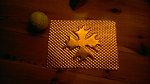
Based on the 2D nature of your posted example, I don't see why you can't do two different halves. One raised and one recessed. The recessed version needs to be adjusted by the thickness of the material you intend to use, and that can be done easily with the. One of the halves needs to be mirrored so that when you flip it over for your press, it will actually mate up with the proper orientation. You will have to adjust the corners by the diameter of the end mil you are using, so you don't have sharp external corners and rounder internal corners...
I did a couple 2 minute down-n-dirty examples below.
Now, if you were talking about an undulating 2.5D male/female, the steps are more involved, but the principle is the same...
Good luck!